An electroplating fixture

A technology of electroplating fixtures and balance bars, applied in the direction of electrolytic components, electrolytic process, etc., can solve the problems of electroplating solution residue, inconvenient, inaccessible electroplating solution, etc., and achieve the effect of increasing utilization rate and convenient installation

Active Publication Date: 2020-09-15
上海裕继金属制品有限公司
View PDF9 Cites 1 Cited by
  • Summary
  • Abstract
  • Description
  • Claims
  • Application Information

AI Technical Summary

Problems solved by technology

[0005] When such parts are fixed by fixtures and placed in the electroplating solution for electroplating; if the ring part faces upwards, since only one end of the outer shell and the inner shell is an open end, when the parts are immersed in the electroplating solution with the open end of the outer shell facing down , air is easy to remain in the shell and the inner shell, so that the electroplating solution cannot enter this part of the space, so that the inner surface of the shell cannot be completely electroplated
In order to ensure that the electroplating solution can enter the shell and be in contact with every position of the inner surface of the shell, it is necessary to immerse the parts in the electroplating solution with the open end of the shell facing upwards; the inner surface of the shell of the parts entering the electroplating solution in this state can be cleaned Fully plated, but when the part is removed from the plating solution, the plating solution remains in the housing
[0006] In the prior art, if this special part is to be processed to ensure complete electroplating, it is necessary to use a process after electroplating to pour out the electroplating solution received in the casing, which is very inconvenient and wastes manpower and material resources

Method used


Image

  • An electroplating fixture
  • An electroplating fixture
  • An electroplating fixture

Examples


Embodiment Construction

[0040] The present invention will be described in further detail below in conjunction with the accompanying drawings.

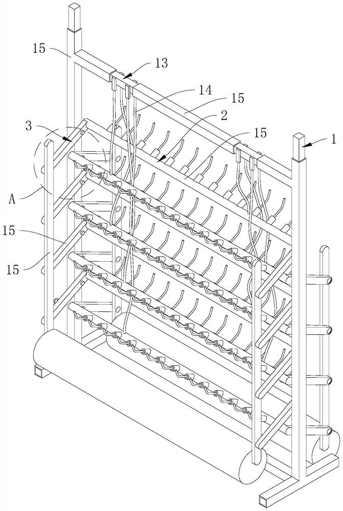
[0041] An electroplating fixture, such as figure 2 As shown, it includes a frame body 1 , a movable part 3 arranged on the frame body 1 , and a fixing part 2 arranged on the movable part 3 .

[0042] Such as Figure 4 As shown, the frame body 1 includes a horizontally arranged I-shaped underframe 11, two vertical rods 12 vertically fixed on the underframe 11, and an I-shaped conductive frame 13 vertically fixed on the upper ends of the vertical rods 12. . Two vertical rods 12 are respectively fixed on both sides of the chassis 11, and the vertical rods 12 and the conductive frame 13 are located on the same vertical plane. The conductive frame 13 includes two vertical sections 131 parallel to the two vertical bars 12, a horizontal section 132 connecting the two vertical sections 131, and the horizontal section 132 is connected with a wire 14 (see figure ...


PUM


Abstract

The invention discloses an electroplating fixture, belongs to the field of electroplating fixtures, and solves the problem of inconvenience to electroplate parts. The electroplating fixture comprisesa frame body, and a fixing piece for fixing parts; and the fixing piece is electrified. The electroplating fixture further comprises a shifting part for shifting the fixing piece; the fixing piece comprises a support rod rotationally connected with the frame body, and multiple plug-in pieces arranged on the support rod; the shifting part comprises a driving piece for driving the support rod to enable the plug-in pieces to rotate on a vertical surface; the shifting part further comprises multiple balance rods rotationally connected to the frame body, and linkage rods connected with the multiplebalance rods; the multiple balance rods are arranged in the vertical direction at intervals; the support rod is fixed on the balance rods; and one ends of the balance rods are rotationally connectedto the linkage rods. Through the linkage rods and the driving piece, the rotation of the plug-in pieces is adjusted to reach the angles of the parts, so that the complete electroplating can be guaranteed, and the effect of not remaining electroplating liquid after taking out of the parts from the electroplating liquid is achieved.

Description

technical field [0001] The invention relates to the field of electroplating fixtures, in particular to an electroplating fixture. Background technique [0002] Electroplating is the process of plating a thin layer of other metals or alloys on the surface of certain metals using the principle of electrolysis. It is a process of using electrolysis to attach a layer of metal film to the surface of metal or other material parts to prevent metal oxidation ( Such as rust), improve wear resistance, electrical conductivity, reflectivity, corrosion resistance and enhance the appearance. Electroplating is generally to put the part into the electroplating solution, the plated metal or other insoluble material is used as the anode (such as zinc), and the part to be plated is used as the cathode, and the solution containing the cation of the plated metal is used as the electroplating solution. [0003] In the prior art, for parts such as cylinders that do not interfere with each other a...

Claims


Application Information

Patent Timeline
Patent Type & Authority Patents(China)
IPC IPC(8): C25D17/08
CPCC25D17/08
Inventor 潘繁华
Owner 上海裕继金属制品有限公司
Why Eureka
Try Eureka