A roller coaster frame device

A roller coaster and frame technology, applied in the field of roller coaster large-scale amusement facilities, can solve the problems of long maintenance period, stress concentration, and easy breakage, etc., and achieve the effects of simplifying the structure, reducing stress concentration, and uniform force distribution

Active Publication Date: 2020-03-24
北京中冶设备研究设计总院有限公司 +1
View PDF6 Cites 0 Cited by
  • Summary
  • Abstract
  • Description
  • Claims
  • Application Information

AI Technical Summary

Problems solved by technology

Due to the increasing number of roller coaster track changes in the existing technology, and the continuous increase in the range of changes and the frequency of direction changes, the alternating loads on the train units continue to increase. In the prior art, this type only relies on the installation of connectors at the tail of the train unit It is difficult to withstand large alternating loads in the same way, and it is easy to break during long-term use, and there is a large potential safety hazard
In the prior art, it is necessary to regularly inspect the train units and the connectors between them. When damage occurs, the roller coaster needs to be shut down for maintenance. Obviously, this way of connecting the train units only by the connectors will also increase the facilities at the same time. Maintenance cost, and the maintenance cycle is longer
[0005] On the other hand, based on the above-mentioned roller coaster that connects the train unit through the connector, in the process of changing direction and changing tracks, since the connector and the train unit are directly welded, the force-bearing position of the frame is at the weld seam during the process. position, and the stress is relatively concentrated here, which affects the strength of the frame to a certain extent, and will also cause certain safety hazards

Method used


Image

  • A roller coaster frame device
  • A roller coaster frame device
  • A roller coaster frame device

Examples


Embodiment Construction

[0019] Embodiments of the roller coaster frame device according to the present invention will be described below with reference to the accompanying drawings. As those skilled in the art would realize, the described embodiments may be modified in various different ways, all without departing from the spirit and scope of the present invention. Accordingly, the drawings and description are illustrative in nature and not intended to limit the scope of the claims. Also, in this specification, the drawings are not drawn to scale, and like reference numerals denote like parts.

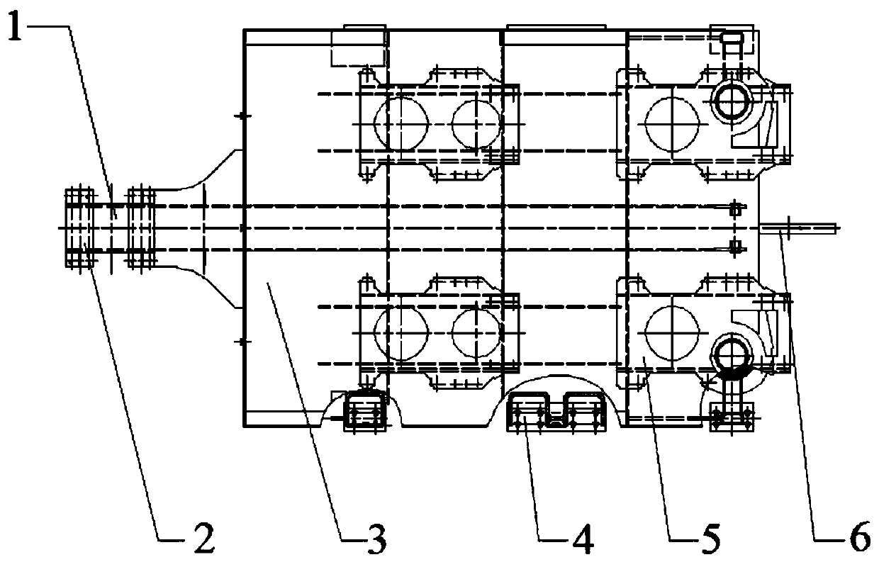
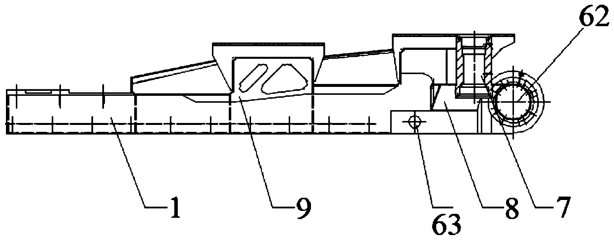
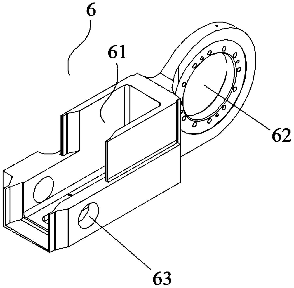
[0020] figure 1 It is a partial sectional view showing the top view structure of the roller coaster frame device described in one embodiment of the present invention. figure 2 is a side view, showing the figure 1 The side structure of the roller coaster frame assembly shown. see figure 1 and figure 2 , The roller coaster frame device described in this embodiment of the present invention includes a mai...


PUM


Abstract

The invention provides a roller coaster frame device. The roller coaster frame device comprises a main beam, a bridge mounting base, a wing plate, brake plate mounting supports, a seat mounting support and a tailstock, wherein the bridge mounting base is fixedly connected with the main beam and located at the head of the main beam; the wing plate is fixedly connected to the main beam, the board ishorizontally arranged on the main beam, and the wing plate is located at the end, not provided with the bridge mounting base, of the main beam; the brake plate mounting supports are arranged on the bottom surface of the wing plate and located at the two sides of the wing plate in the extending direction of the main beam; the seat mounting support is arranged on the surface of the wing plate; thetailstock is fixedly connected to the main beam and is located at the tail of the main beam, and the tailstock is used for being connected with a spherical hinge connector. The roller coaster frame device has the advantages that the alternating load withstood by the connection between roller coaster train units can be improved, the breakage of the connectors between the roller coaster train unitscan be avoided, the stress intensity of the joints when the train turns or changes rails can be improved, the safety hazards during train running can be reduced, the service life of the train can be prolonged, and the inspection and repair cost can be reduced.

Description

technical field [0001] The invention relates to a roller coaster large amusement facility, in particular to a roller coaster frame device. Background technique [0002] Large roller coasters are common amusement facilities in large amusement parks, which mainly include trains, driving tracks, columns, traction systems and braking systems. The operating principle of the roller coaster is that the traction system pulls the train to the highest point of the running track, and then the traction system is separated from the train, and then the train runs quickly along the running track under the action of its own gravity and inertia, relying on the mutual transformation of its own potential energy and kinetic energy , and finally the braking system operates, causing the train to decelerate and return to the station. [0003] The train is multi-section, and each train unit is connected by a connector, and each unit is connected to the bridge frame through a wheel train. In this w...

Claims


Application Information

Patent Timeline
Patent Type & Authority Patents(China)
IPC IPC(8): A63G21/14A63G21/06
CPCA63G21/06A63G21/14
Inventor 孙亚伟张金利王国平师学斌黄羽牟世学孟洁马超宇
Owner 北京中冶设备研究设计总院有限公司
Why Eureka
Try Eureka