Flue gas plume removing system and plume removing method thereof

A flue gas and dewhitening technology, applied in separation methods, chemical instruments and methods, gas treatment, etc., can solve the problems of high countercurrent tower height, easy height limitation, and large countercurrent resistance, etc. Dry bulb temperature, noise reduction effect

Pending Publication Date: 2019-03-29
HEIMDALLR SHANGHAI ENERGY SAVING TECH
View PDF13 Cites 0 Cited by
  • Summary
  • Abstract
  • Description
  • Claims
  • Application Information

AI Technical Summary

Problems solved by technology

However, the high wind speed of the traditional counterflow tower makes the height of the counterflow tower too high, which is easy to be limited in the renovation project, and the counterflow resistance is too large, and the noise is relatively large

Method used


Image

  • Flue gas plume removing system and plume removing method thereof
  • Flue gas plume removing system and plume removing method thereof
  • Flue gas plume removing system and plume removing method thereof

Examples


Embodiment 1

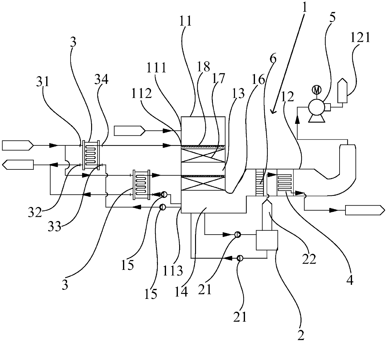
[0064] Such as figure 1 As shown, this embodiment discloses a flue gas de-whitening system, the flue gas de-whitening system includes a de-whitening tower 1 and a regeneration device 2, the de-whitening tower 1 includes a downstream part 11 and a cross-current part 12, the downstream part The top of 11 is provided with a smoke inlet 111 , one end of the cross-flow part 12 is connected to the bottom of the downstream part 11 , and the other end of the cross-flow part 12 is provided with a smoke outlet 121 . The flue gas to be dewhitened enters into the dewhitening tower 1 through the flue gas inlet 111, moves downstream from top to bottom at the upper end of the downstream part 11, and then enters the cross-flow part 12, moves cross-flow in the cross-flow part 12 and flows from The flue gas outlet 121 is discharged. The flue gas is discharged after passing through the downstream part 11 and the cross-flow part 12, the wind speed is low, the power consumption is low, the height...

Embodiment 2

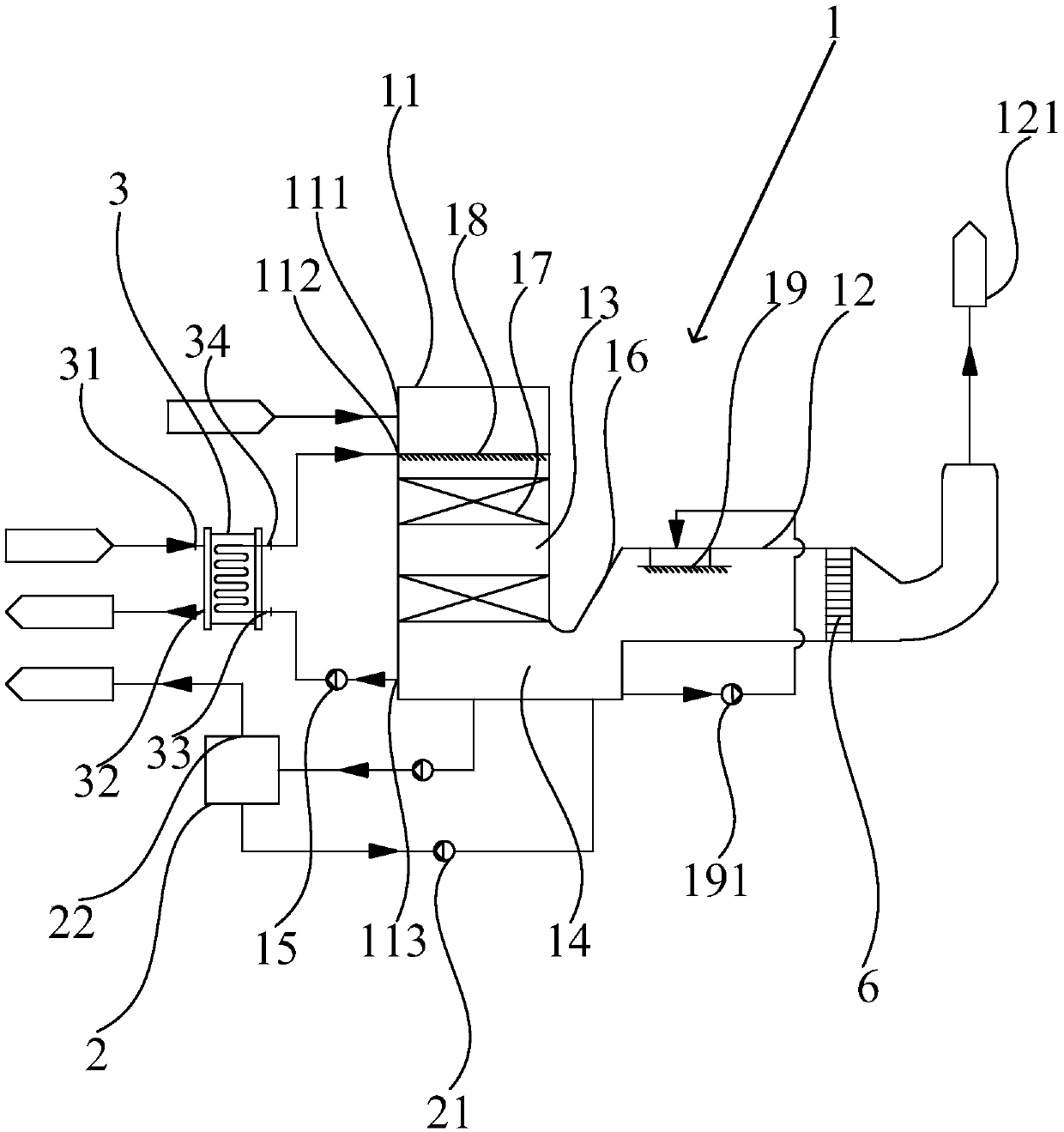
[0086] Such as figure 2 As shown, the difference between this embodiment and Embodiment 1 is that in the flue gas de-whitening system of this embodiment, at least one second solution spraying device 19 is arranged in the cross flow part 12, and the second solution spraying device 19 is connected to the top of the cross-flow part 12, and the second solution spraying device 19 communicates with the solution storage area 14 through a pipeline, and a third solution pump 191 is provided on the pipeline. Through the second solution spraying device 19, the flue gas is directly and fully contacted with the solution again to ensure the removal of water vapor in the flue gas, further enhancing the effect of removing white feathers from the flue gas. After the solution is in contact with the flue gas, it will flow to the solution storage area 14 through the guide part 16, so as to achieve the effect of circulation on the whitening of the flue gas. At the same time, the pressure of the ...

Embodiment 3

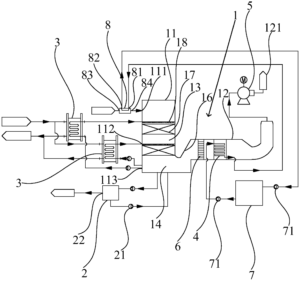
[0090] Such as image 3 As shown, the difference between this embodiment and Embodiment 1 is that, in the flue gas whitening system of this embodiment, the heat source outlet 22 of the regeneration device 2 is not connected to the flue gas reheater 4, and the regeneration device 2 The secondary steam generated in the process is directly utilized and recovered.

[0091] The flue gas whitening system also includes a flue gas preheater 8 and a water tank 7. The outer wall of the flue gas preheater 8 is provided with a water inlet 81, a water outlet 82, an air inlet 83 and an air outlet 84, and the air outlet 84 is connected to The flue gas inlet 111 is connected to the whitening tower 1, the water inlet 81 is connected to the flue gas reheater 4, the water outlet 82 is connected to the water tank 7, the flue gas preheater 8, the water tank 7 and the flue gas reheater 4 They are connected and form a circulating water circuit. Water is stored in the water tank 7, and the water ci...


PUM


Abstract

The invention discloses a flue gas plume removing system and a plume removing method thereof. The flue gas plume removing system comprises a plume removing tower and a regeneration device, the plume removing tower includes a parallel-flow portion and a cross-flow portion, a smoke inlet is arranged at the top of the parallel-flow portion, one end of the cross-flow portion communicates with the bottom of the parallel-flow portion, the other end of the cross-flow portion is provided with a flue gas outlet, at least one spray inlet is arranged on the outer wall surface of the parallel-flow portion, a flue gas spraying area and a solution storage area are sequentially arranged in the parallel-flow portion from top to bottom, the flue gas inlet is positioned above the flue gas spraying area, thespray inlet is communicated with the flue gas spraying area, the solution storage area is communicated with the regeneration device and forms a solution loop, the bottom of the parallel-flow portionis communicated with the spray inlet, and a circulation loop is formed between the solution storage area and the spray inlet. The plume removing method utilizes the flue gas plume removing system as described above, so as to effectively absorb the plume in the flue gas and to achieve the flue gas plume removing. The height of the plume removing tower is lowered, and the noise is reduced.

Description

technical field [0001] The invention relates to a system for removing white feathers from flue gas and a method for removing white feathers. Background technique [0002] At present, in the field of flue gas treatment, desulfurization, denitrification and dust removal are mainly considered. Desulfurization technology is widely used in power plants and roasters and other related boiler factories. The equipment in desulfurization towers is also widely used. Regarding the dewhitening of flue gas, in the absorption tower Class structures are rarely reported. At the same time, the conventional absorption tower structure generally adopts a countercurrent tower, and the equipment layout and flue direction in the countercurrent tower. However, the high wind speed of the traditional counterflow tower makes the height of the counterflow tower too high, which is easy to be limited in height in the renovation project, and the counterflow resistance is too large, and the noise is relati...

Claims


Application Information

Patent Timeline
Patent Type & Authority Applications(China)
IPC IPC(8): B01D53/26B01D53/14
CPCB01D53/14B01D53/263B01D2257/80
Inventor 马元赵怀超徐敬玉白亮
Owner HEIMDALLR SHANGHAI ENERGY SAVING TECH
Why Eureka
Try Eureka