A pneumatically controlled double-stage shear precision separation device

A precise separation and pneumatic control technology, applied in shearing devices, pipe shearing devices, accessories of shearing machines, etc., can solve the problems of large cutting force, complex structure, mold wear, etc., to improve the quality of blanking and design structure. Simple and efficient blanking

Inactive Publication Date: 2021-01-29
XIAN UNIV OF SCI & TECH
View PDF7 Cites 0 Cited by
  • Summary
  • Abstract
  • Description
  • Claims
  • Application Information

AI Technical Summary

Problems solved by technology

At present, the traditional blanking devices with a high degree of application in this field mainly include devices such as sawing and cutting, lathe cutting, disc milling cutter cutting and punching shearing, but these existing production devices still have limitations in actual industrial production to varying degrees. Complex structure, narrow scope of application, low production efficiency, low material utilization rate, poor cross-section quality of rods and tubes, large cutting force, high noise, low mold life, high energy consumption, serious environmental pollution by metal cutting fluid, etc.
In recent years, although new blanking devices have emerged in the industry and improved some of the above-mentioned defects to a certain extent, there are still corner collapses and burrs, large clamping force required, and mold Severe wear, low life, complex mechanism, small application range, local shear deformation, large impact vibration, difficult load loading, secondary damage to the section, etc., affect production efficiency and product processing quality

Method used


Image

  • A pneumatically controlled double-stage shear precision separation device
  • A pneumatically controlled double-stage shear precision separation device
  • A pneumatically controlled double-stage shear precision separation device

Examples


Embodiment Construction

[0013] The technical solutions in the embodiments of the present invention will be further described below in conjunction with the accompanying drawings. Based on the embodiments of the present invention, all other embodiments obtained by persons of ordinary skill in the art without making creative efforts belong to the protection scope of the present invention.

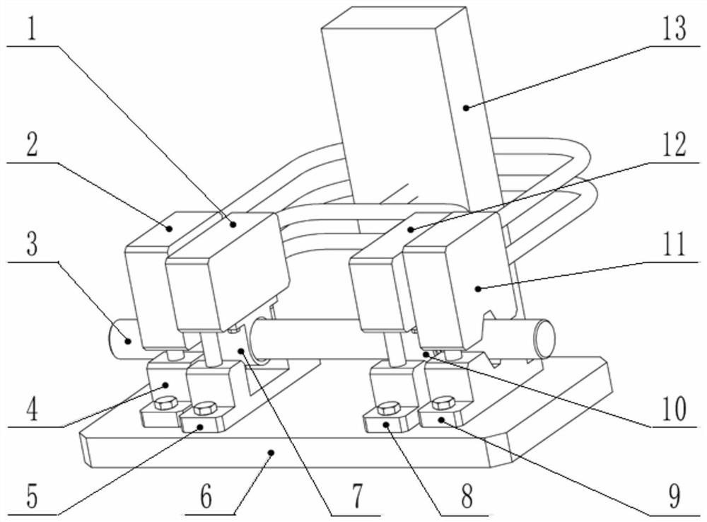
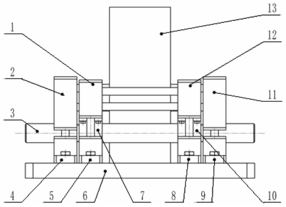
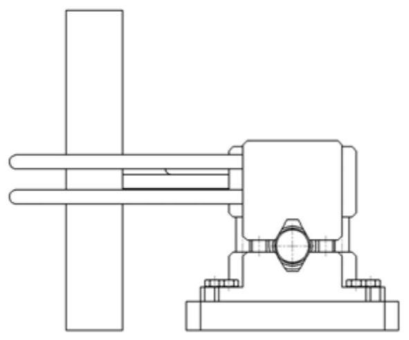
[0014] Referring to the accompanying drawings, the pneumatically controlled double-stage shear precision separation device of the present invention is mainly composed of a pneumatic system 13 and a mechanical structure. The pneumatic system 13 is used as the power source of the device, and the mechanical structure includes a base 6 and two groups of rod and tube material clamping mechanisms symmetrically arranged on the left and right sides of the base 6 and two groups of rod and tube material pneumatic forging and shearing mechanisms. mechanism. The rod and pipe material clamping mechanism is composed of a left V-s...


PUM


Abstract

The invention relates to a pneumatically controlled double-stage shear precision separation device for cutting metal rods and tubes. It consists of a pneumatic forging and shearing mechanism for rods and tubes that is separated from the inner side of the rod and tube material clamping mechanism. The rod and tube material clamping mechanism includes a V-shaped support and a V-shaped cylinder that is located above the V-shaped support and driven by a pneumatic system. The block; rod and tube material pneumatic forging and shearing mechanism includes an impact cylinder base and an impact cylinder located above the impact cylinder base and driven by a pneumatic system, and a rod and tube material forging sleeve is installed at the lower end of the impact cylinder. When working, the pneumatic system controls the cylinder V-shaped pressing block and the V-shaped support to clamp the metal rod and tube material, and then the pneumatic system controls two impact cylinders to drive the rod and tube material forging sleeve to simultaneously carry out the metal rod and tube material at both ends. Forging and pressing, and finally complete the cutting work of the rod and tube material.

Description

technical field [0001] The invention belongs to the technical field of mechanical processing equipment, and relates to a pneumatically controlled double-stage shearing precision separation device used for cutting and processing metal rods and tubes. Background technique [0002] As the most basic blank, metal rod tube is widely used in machinery manufacturing industry. If metal rods and tubes are to be put into mechanical manufacturing, the first thing to do is blanking, and the quality of blanking will have a great impact on subsequent processing quality, production efficiency, product effect and production cost. At present, the traditional blanking devices with a high degree of application in this field mainly include devices such as sawing and cutting, lathe cutting, disc milling cutter cutting and punching shearing, but these existing production devices still have limitations in actual industrial production to varying degrees. Complex structure, narrow scope of applicat...

Claims


Application Information

Patent Timeline
Patent Type & Authority Patents(China)
IPC IPC(8): B23D21/00B23D27/00B23D33/02B23D33/00
CPCB23D21/00B23D27/00B23D33/00B23D33/02
Inventor 刘戳钟斌于正洋李雪伍吕源
Owner XIAN UNIV OF SCI & TECH
Why Eureka
Try Eureka