Eureka AIR delivers breakthrough ideas for toughest innovation challenges, trusted by R&D personnel around the world.

Offshore working ship with variable balance wing

A technology of balance wings and work boats, which is applied in the direction of using hydrofoils to act on the surrounding water to reduce ship motion, ship safety, and equipment to reduce ship motion. Short and other problems, to achieve the effect of improving the ability of special operations at sea, increasing the resistance of the hull to lateral stress, and improving the overall balance ability

Pending Publication Date: 2019-03-29
HAINAN HENGXIN CIVIL ENG CONSTR
View PDF8 Cites 2 Cited by
  • Summary
  • Abstract
  • Description
  • Claims
  • Application Information

AI Technical Summary

Problems solved by technology

[0003] Multihull ships have the advantages of good stability, safety and comfort, and flexible maneuvering, but the structure is complex, the swing period is short, and the intermediate structure is weak
In view of this, most of the ships currently adopt monohull structure, which can basically guarantee the normal use of conventional ships such as transport ships, fishing boats, port ships, etc., but for engineering ships used for special operations, such as dredgers, lifting Heavy ships, piling ships, cable laying ships, etc. will change the direction of the force due to the change of the working direction during the operation process, which will cause engineering ships, especially crane ships, to easily capsize due to uneven balance force, resulting in disastrous consequences Therefore, the conventional practice in the shipbuilding industry is to increase the size and tonnage of the hull, and adopt the model of large size and large tonnage corresponding to small operating capacity to increase the anti-overturning capability, but this results in increased shipbuilding costs, increased operating costs, and seaworthiness. Waterway requirements and other issues

Method used


Image

  • Offshore working ship with variable balance wing
  • Offshore working ship with variable balance wing
  • Offshore working ship with variable balance wing

Examples


Embodiment

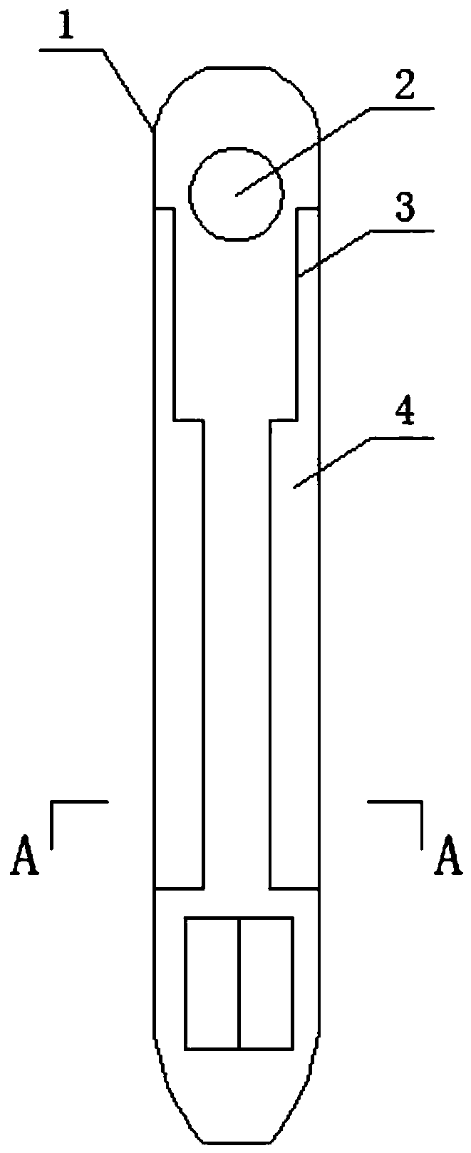
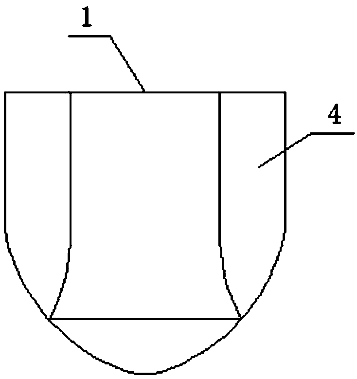
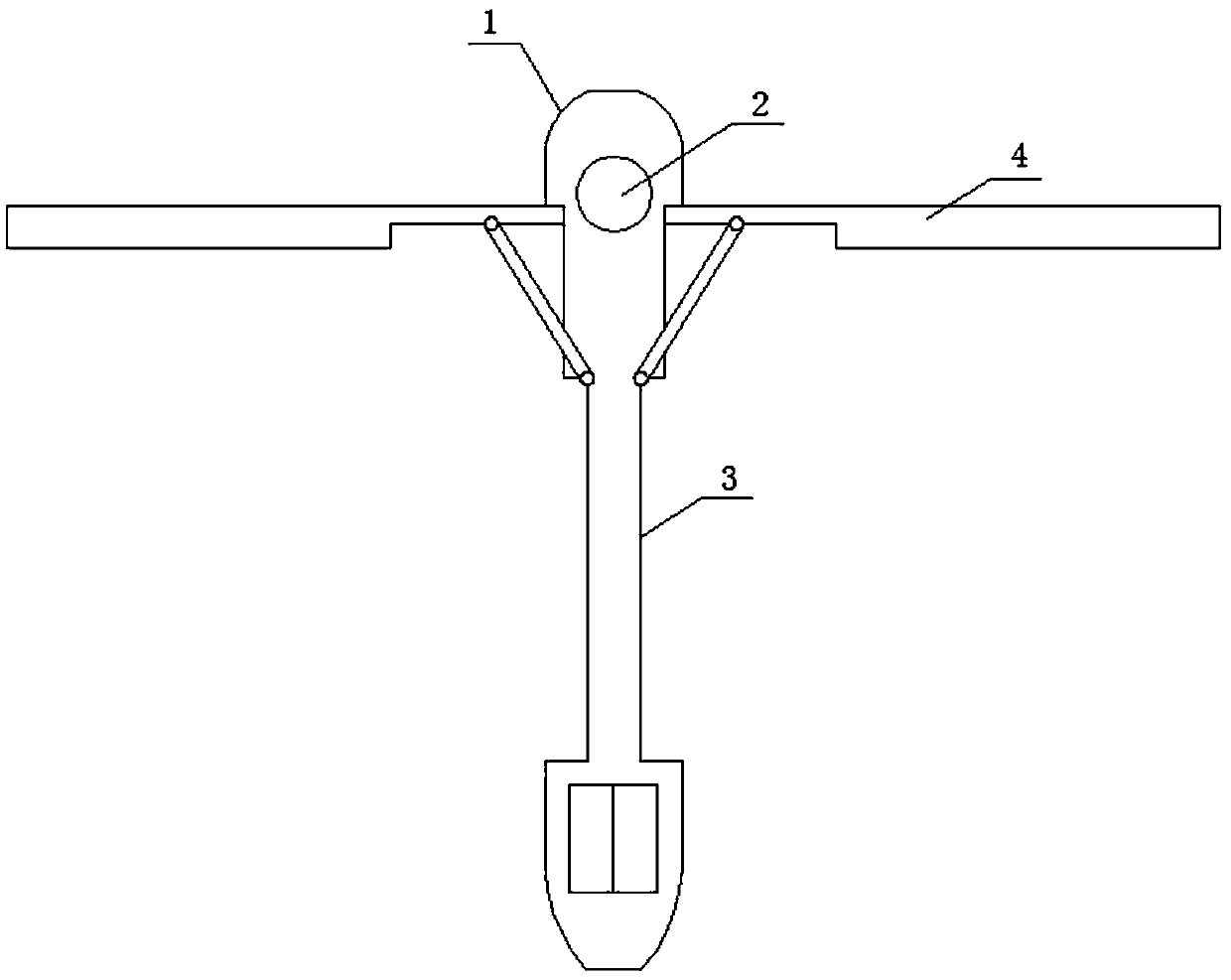
[0021] exist Figure 4 , 5 In the structure shown in , 6, the variable balance wing offshore operation ship provided by the present invention is specifically applied to the crane ship, and the rotating platform base is set on the working platform 2, and the boom 5 is set on the rotating platform base. , the counterweight 6 is set movable on the balance wing 4, and the base of the rotating platform is connected with the counterweight 6 through the traction cable mechanism 7. seat rotation) counterweight 6 moves in the opposite direction to achieve counterweight balance, that is, when the boom 5 rotates clockwise, the counterweight on the left balance wing moves outward, and the counterweight on the right balance wing moves inward Move to achieve counterweight balance and vice versa.

[0022] The variable balance wing marine operation ship provided by the present invention is not only used on crane ships, but also can be applied to engineering work ships such as dredgers, pili...


PUM


Abstract

The invention belongs to the field of offshore special operation equipment, and relates to an offshore working ship with a variable balance wing, which comprises a ship body, a propulsion device, auxiliary equipment thereof and electric equipment, wherein the side part of the ship body corresponding to a working platform is designed into a concave structure, the side part of the ship body with theconcave structure is hinged with the balance wing, and the ship body is provided with a power control device for controlling the running state of the balance wing. According to the invention, a structure form of the variable balance wing is adopted on the basis of a structure of a single ship, the normal navigation of the working ship is not influenced, the balance wing can be unfolded to advancethe buoyancy during the working, the working capability and the lateral stress resistance of the ship body are effectively increased, the whole balance capability is improved and the anti-overturningstability is improved, the offshore special working capability is improved under the condition of the same hull tonnage, and the ship can be better adapted to the requirements of special working by arranging corresponding facilities on the balance wing.

Description

technical field [0001] The invention belongs to the field of marine special operation equipment, and relates to an operation ship, in particular to a variable balance wing sea operation ship. Background technique [0002] As a means of transportation that can be transported or operated in waters, ships have different technical performance, equipment and structural types according to different use requirements. With the continuous advancement and renewal of science and technology, the types of ships continue to increase. According to their uses, they can be divided into transportation boats, fishing boats, engineering boats and harbor boats, etc. [0003] Multihull ships have the advantages of good stability, safety and comfort, and flexible maneuvering, but their structures are complex, their swing periods are short, and their intermediate structures are relatively weak. In view of this, most of the ships currently adopt monohull structure, which can basically guarantee the...

Claims


Application Information

Patent Timeline
Patent Type & Authority Applications(China)
IPC IPC(8): B63B39/06B63B43/08
CPCB63B39/062B63B43/08
Inventor 王恒国
Owner HAINAN HENGXIN CIVIL ENG CONSTR
Why Eureka
Eureka Blog
Learn More