Eureka AIR delivers breakthrough ideas for toughest innovation challenges, trusted by R&D personnel around the world.

Multi-head Energy Dissipating Barge Device for Large Flow Cutter Suction Ship

A cutter-suction ship with high flow rate, which is applied in the direction of earth mover/shovel, mechanically driven excavator/dredger, construction, etc. It can solve the problems of occupying a large water area, affecting navigation, and not being able to discharge long-distance. Achieve the effects of reducing the occupied space, accelerating the precipitation speed and broad application prospects

Active Publication Date: 2017-09-05
南京长瑞建设发展有限公司
View PDF4 Cites 0 Cited by
  • Summary
  • Abstract
  • Description
  • Claims
  • Application Information

AI Technical Summary

Problems solved by technology

[0004] 1. The cutter suction dredger is used for fixed-point construction. Since its construction needs to be anchored for positioning and take over the pipeline to discharge mud, it occupies a large water area. If it is used for channel maintenance construction, it cannot actively avoid sailing ships in time;
[0005] 2. The pipeline is generally connected and discharged by floating tube or floating tube plus submersible tube. The floating tube used will affect the navigation. The submersible tube used is easy to be buried by sediment, and it is difficult to maintain and float;
[0006] 3. The dredged soil is limited by the discharge distance of the cutter suction dredger, and is generally discharged to the deep water area outside the channel near the dredged area or filled to the tidal flat, and cannot be discharged at a long distance

Method used


Image

  • Multi-head Energy Dissipating Barge Device for Large Flow Cutter Suction Ship
  • Multi-head Energy Dissipating Barge Device for Large Flow Cutter Suction Ship

Examples


Embodiment Construction

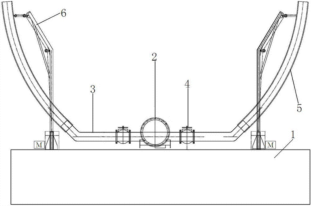
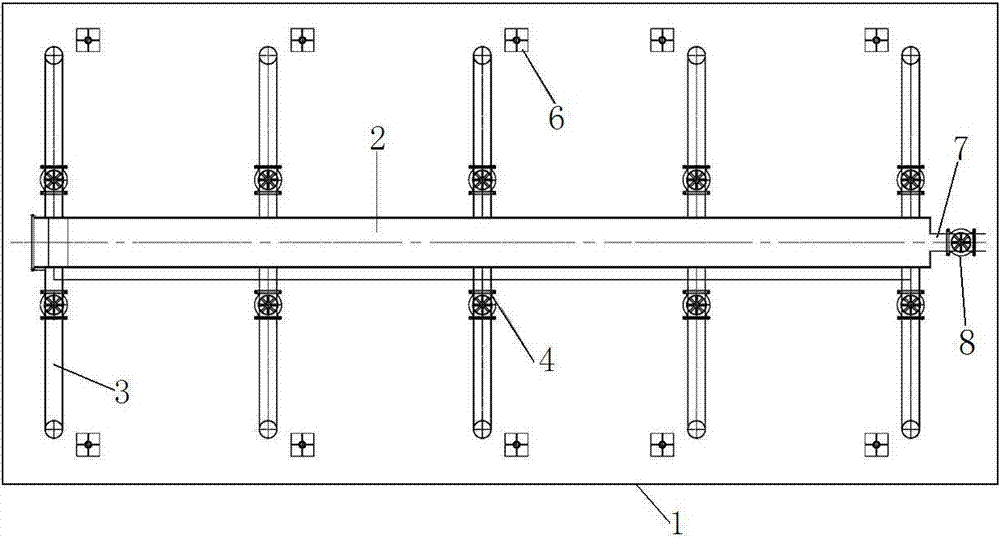
[0023] Refer to attached Figure 1~2 The multi-head energy-dissipating barge device for large-flow cutter suction ships includes an installation platform 1, a main pipe 2, a mud outlet pipe 3, a control valve 4, a mud outlet hose 5, a liftable support 6, a multi-purpose mud outlet 7 and control Valve two 8.

[0024] The installation platform 1 is a floating pontoon, and a liftable support 6 is installed on the upper surface of the installation platform 1. The main pipeline 2 is placed on the upper end surface of the installation platform 1, and mud outlet pipes 3 are arranged on both sides of the main pipeline 2 pipe walls. The outer end of mud pipe 3 is covered with a mud hose 5, and the mud hose 5 is hung on the lower end of the liftable support 6 by a steel wire, and the steel wire is wound on the pulley of the liftable support 6, and a Motor, the tail end of steel wire is connected on the motor output shaft, controls the lifting of mud hose 5 by motor.

[0025] A control...


PUM


Abstract

The multi-head energy-dissipating barge device for a large-flow cutter suction ship of the present invention relates to a dredged soil barge operation system for a cutter suction dredger, in particular to a barge barge for dredging mud excavated by a cutter suction dredger. The multi-head energy-dissipating barge device for a large-flow cutter suction ship includes an installation platform, a main pipe, a mud outlet pipe, a control valve 1, a mud outlet hose, a liftable support, a multi-purpose mud outlet, and a control valve 2. The installation platform is a floating pontoon, and a liftable support is installed on the upper surface of the installation platform. The main pipeline is placed on the upper surface of the installation platform, and a mud outlet pipe is arranged on both sides of the pipe wall of the main pipeline. The outer end of the mud outlet pipe is fitted with a The mud hose, the mud hose is hung on the lower part of the liftable support through the steel wire, the steel wire is wound on the pulley of the liftable support, the motor is installed at the lower part of the liftable support, and the tail end of the steel wire is connected to the output shaft of the motor. The lifting of the mud hose is controlled by the motor. A control valve 1 is installed on the mud outlet pipe to control the opening of the mud outlet pipe.

Description

technical field [0001] The multi-head energy-dissipating barge device for a large-flow cutter suction ship of the present invention relates to a dredged soil barge operation system for a cutter suction dredger, in particular to a barge barge for dredging mud excavated by a cutter suction dredger. Background technique [0002] In channel maintenance operations, cutter suction dredgers have the advantage of being able to continuously output large flow of dredged soil. Compared with traditional cutter suction dredgers, the traditional straight discharge construction process uses a large number of pipelines and occupies a large area of ​​water. The construction has a great impact on navigation, many waterways are not suitable, and the way of direct discharge by cutter suction dredgers cannot be constructed in many areas, which has great limitations. [0003] The disadvantages of the traditional process of cutter suction dredger direct discharge in channel maintenance: [0004] ...

Claims


Application Information

Patent Timeline
Patent Type & Authority Patents(China)
IPC IPC(8): E02F5/28E02F3/90E02F7/10
Inventor 刘义武沈继权崔长会王平周建忠翟华薛仑陈海培
Owner 南京长瑞建设发展有限公司
Why Eureka
Eureka Blog
Learn More