
A composite beam structure

A technology of superimposed beams and supporting beams, applied to truss structures, joists, girders, etc., can solve the problems of low structural stability, easy relative displacement between main supporting beam 1 and prefabricated beam 4, etc., and achieve lifting connection Stability, the effect of improving the connection smoothness

Active Publication Date: 2020-10-16
浙江大经住工科技有限公司
View PDF5 Cites 0 Cited by
  • Summary
  • Abstract
  • Description
  • Claims
  • Application Information

AI Technical Summary

Problems solved by technology

[0005] However, as the service time becomes longer, due to the planar contact between the upper end of the main support beam 1 and the two prefabricated beams 4, the relative displacement between the main support beam 1 and the prefabricated beams 4 is likely to occur, and the structural stability is not high

Method used


Image

  • A composite beam structure
  • A composite beam structure
  • A composite beam structure

Examples


Embodiment Construction

[0036] The present invention will be described in further detail below in conjunction with the accompanying drawings.

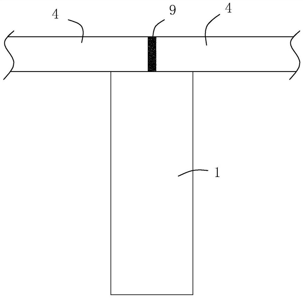
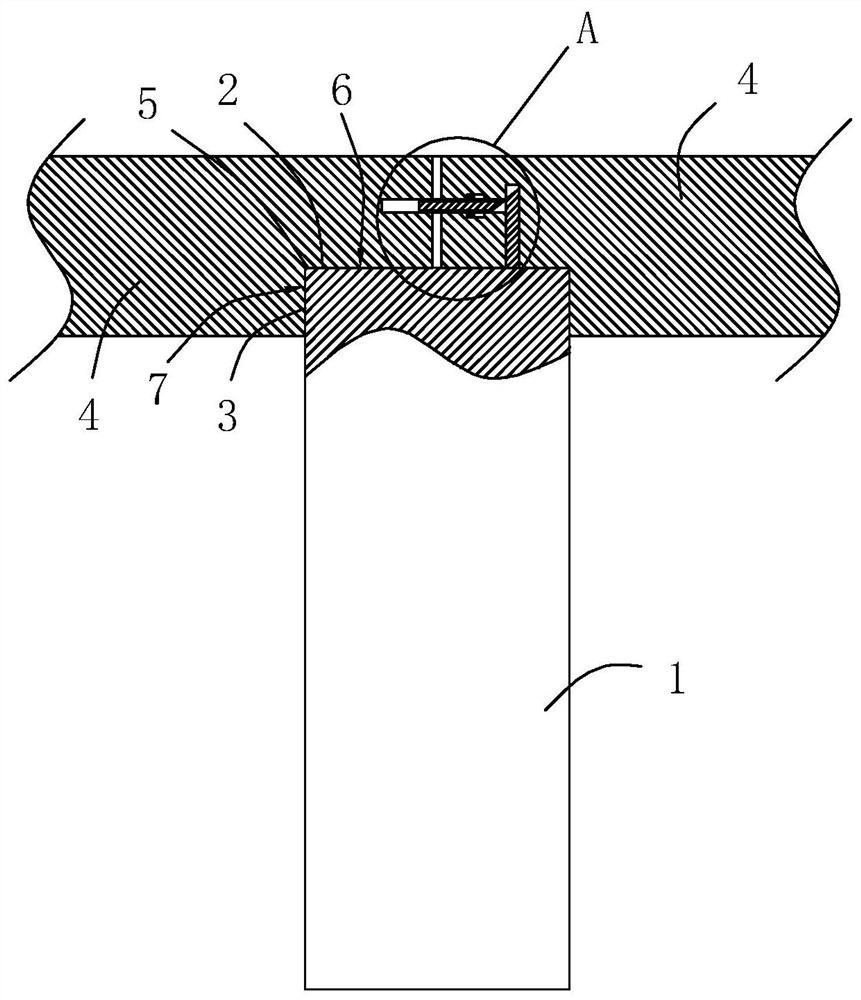
[0037] refer to figure 2 , is a composite beam structure disclosed in the present invention, which includes a vertical support beam 1 and two horizontal prefabricated beams 4. In this embodiment, both the support beam 1 and the prefabricated beam 4 are square in shape Beam, the butt joint point between two prefabricated beams 4 is located at the upper end of the supporting beam 1 .

[0038] Among them, refer to figure 2 , the support beam 1 includes an upper end surface 2 and a side end surface 3, the upper end surface 2 is arranged horizontally, two side end surfaces 3 are provided, the two side end surfaces 3 are oppositely arranged, and each side end surface 3 is arranged vertically.

[0039] refer to figure 2 , the end of the prefabricated beam 4 is provided with a notch 5, and the two adjacent side walls in the notch 5 are respectively a horizontal...


PUM


Abstract

The invention relates to a superposed beam structure. The superposed beam structure structurally comprises a vertical supporting beam and two horizontal precast beams, the connecting point between thetwo precast beams is located at the upper end of the supporting beam, and the lateral surface of the supporting beam comprises an upper end face and a lateral end face. A notch is formed in the end of the precast beam, two adjacent side walls in the notch include the horizontal side wall and the vertical side wall, the horizontal side wall is attached to the upper end face of the supporting beam,and the vertical side wall is attached to the lateral end face of the supporting beam. By using the connecting way, the stability of connection between the main supporting beam and the precast beam can be greatly improved, even if a trend of lateral displacement is generated between the main supporting beam and the precast beam, and the stability of connection between the notch and the main supporting beam can be kept through the cooperation way between the notch and the main supporting beam. In the superposed beam structure, toxic and contaminated materials are not used, the overall servicelife of the superposed beam is long, and frequent maintenance is not needed.

Description

technical field [0001] The invention relates to the technical field of construction engineering structural beams, in particular to a composite beam structure. Background technique [0002] The composite beam is a beam that is poured and tamped in two times. The first time the prefabricated beam 4 is made in the prefabrication field; the second time is carried out at the construction site. connected into a whole. [0003] Existing composite beam structure as attached figure 1 As shown, it mainly includes a support beam 1 supported on the ground, and the prefabricated beam 4 is horizontally hoisted and placed on the upper end of the support beam 1 . [0004] Since the overall length of the prefabricated beam 4 is limited, if a longer prefabricated beam 4 is to be used, a plurality of prefabricated beams 4 need to be butted at the ends. figure 1 The placement method shown is that the opposite ends of the two prefabricated beams 4 are respectively placed on the upper end of t...

Claims


Application Information

Patent Timeline
Patent Type & Authority Patents(China)
IPC IPC(8): E04C3/20E04B1/21
CPCE04B1/21E04C3/20
Inventor 李小明王亮林云敏刘于峰周松松
Owner 浙江大经住工科技有限公司
Features
  • Generate Ideas
  • Intellectual Property
  • Life Sciences
  • Materials
  • Tech Scout
  • Unparalleled Data Quality
  • Higher Quality Content
  • 60% Fewer Hallucinations
Learn More