
Novel limiter shell body structure

A technology of shell structure and limiter, which is applied to the fastening devices of wings, building structures, building fastening devices, etc., and can solve the problems of poor practicability

Inactive Publication Date: 2019-03-29
FENGYE TIMS WUHU AUTO PARTS CO LTD
View PDF6 Cites 2 Cited by
  • Summary
  • Abstract
  • Description
  • Claims
  • Application Information

AI Technical Summary

Problems solved by technology

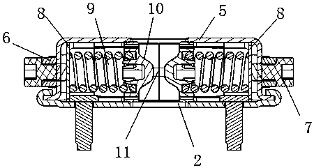
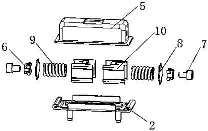
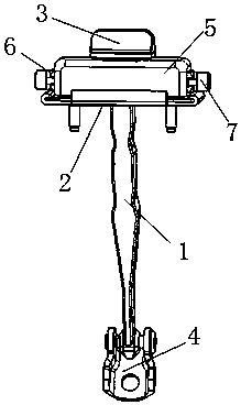
[0003] Aiming at the deficiencies of the prior art, the present invention provides a novel limiter housing structure, which solves the problem that the traditional limiter structure is too simple to cause poor practicability. The present invention adopts the following to solve the technical problem Technical solution: including a limit arm, a shell cover is installed on the limit arm, a limit bracket and a stopper are respectively provided at the top and bottom of the limit arm, the top of the shell cover is covered with a shell, and the left and right sides of the shell are welded Nuts, the two nuts are threadedly connected with bolts, the other ends of the two bolts extend to the inside of the housing, the other ends of the two bolts are connected with baffles, the other ends of the 2 baffles are provided with springs, 2 The other end of the spring is connected with a slider, and a limit rod is arranged between the two sliders, and the two sliders are respectively located on the left and right sides of the limit arm

Method used


Image

  • Novel limiter shell body structure
  • Novel limiter shell body structure
  • Novel limiter shell body structure

Examples


Embodiment Construction

[0012] In order to deepen the understanding of the present invention, the present invention will be further described below in conjunction with the examples, which are only used to explain the present invention, and do not constitute a limitation to the protection scope of the present invention.

[0013] Such as Figure 1-3 As shown, the present embodiment provides a novel housing structure of the limiter, including a limiter arm 1, a shell cover 2 is installed on the limiter arm 1, and a limiter bracket 3, The stopper 4, the top of the shell cover 2 is covered with a shell 5, the outer left and right sides of the shell 5 are welded with nuts 6, the two nuts 6 are screwed with bolts 7, and the other ends of the two bolts 7 are extended to the shell 5. Inside, the other ends of the two bolts 7 are connected with retaining pieces 8, the other ends of the two retaining pieces 8 are provided with springs 9, the other ends of the two springs 9 are connected with sliders 10, and the...


PUM


Abstract

The invention provides a novel limiter shell body structure. The novel limiter shell body structure comprises a limit arm, wherein a shell cover is installed on the limit arm; a limit support and a stop block are arranged at the top end and the bottom end of the limit arm separately; a shell body sleeves the top of the shell cover; nuts are welded to the left side and the right side outside the shell body separately; the two nuts are in threaded connection with a bolt separately; the other end of each of the two bolts stretches into the shell body; a stop sheet is connected to the other end ofeach of the two bolts; a spring is arranged at the other end of each of the two stop sheets; a slide block is connected to the other end of each of the two springs; a limit rod is arranged between the two slide blocks; and the two slide blocks are located at the left side and the right side of the limit arm separately. According to the novel limiter shell body structure, the two nuts are welded to the two sides of the shell body, the two bolts are installed separately, the stop sheets are compressed by adjusting the screwing dimensions of the bolts, and then the dimensions of a cavity of theshell body are adjusted; and the influence of manufacturing tolerance among a plurality of parts is balanced through adjustment for an operation force of a limiter, so that the actual operation forceof the limiter much approximates to a design theoretical value.

Description

technical field [0001] The invention relates to the technical field of stopper assemblies, in particular to a novel stopper housing structure. Background technique [0002] The car stopper is an auxiliary part connecting the car door and the car body. Its main function is to limit the opening angle of the car door. Its use frequency is very high. The structure of the traditional stopper is too simple. The cavity is fixed, and it is inconvenient to adjust the various parts of the stopper, so that the influence caused by component tolerances cannot be reduced or avoided, which reduces the accuracy of the stopper, is not conducive to the use of the stopper, and reduces the limit Therefore, it is very necessary to solve the above problems. Contents of the invention [0003] Aiming at the deficiencies of the prior art, the present invention provides a novel limiter housing structure, which solves the problem that the traditional limiter structure is too simple to cause poor pr...

Claims


Application Information

Patent Timeline
Patent Type & Authority Applications(China)
IPC IPC(8): E05C17/12
CPCE05C17/12
Inventor 汪冬冬王孝军
Owner FENGYE TIMS WUHU AUTO PARTS CO LTD
Learn More