Constant pressure full-balanced type floating side plate

A floating side plate, balanced technology, applied in the direction of rotary piston type/swing piston type pump components, machines/engines, pump components, etc., can solve the problem that the gear oil pump cannot reach the service life and effect, the formation and maintenance of friction pairs Difficulties, reduce the mechanical efficiency of the gear oil pump, etc., to achieve the effect of reducing unit energy consumption, improving the formation of friction pairs, and high reliability

Active Publication Date: 2009-11-04
HEFEI CHANGYUAN HYDRAULICS
View PDF0 Cites 4 Cited by
  • Summary
  • Abstract
  • Description
  • Claims
  • Application Information

AI Technical Summary

Problems solved by technology

[0003] For the hydraulic gear oil pump of ordinary design, due to its inherent structure, the gear oil pump faces the following problems with the increase of the pressure level: First, the radial hydraulic pressure borne by the gear is greatly increased, such as Figure 4 As shown, it is required to reduce the hydraulic radial force borne by the gear or to increase the strength of the gear 1 structurally; secondly, it is more and more difficult to form and maintain the friction pair between the lower side plate and the gear under high temperature, high pressure and high speed, such as Figure 3a , Figure 3b and Figure 3c As shown, the conventional high pressure side 23 and low pressure side 24 on the back side of the side plate, on both sides of the sealing ring groove 22 are in the form of flat plates with the same plane height, and the chamfer 21 of the enlarged high pressure area is set on the front side of the side plate, which makes the The backside of side panel 2 produces Figure 3c The unbalanced hydraulic thrust f2 shown, compared with the balanced hydraulic thrust f1 on the front side of the side plate, makes the thrust on the side plate form a torque, so the side plate 2 cannot effectively fit on the gear end surface, forming a local contact
With the increase of pressure, temperature and speed, the oil film between the friction pairs is also easily damaged, and the gear oil pump will not achieve the expected service life and effect; the third is that the gear oil pump under the conventional design needs to ensure the volumetric efficiency. The thrust is insufficient and uneven, so the compression of the seal can only be increased, which can only make the side plate and the gear fit locally, but this will greatly reduce the mechanical efficiency of the gear oil pump

Method used


Image

  • Constant pressure full-balanced type floating side plate
  • Constant pressure full-balanced type floating side plate
  • Constant pressure full-balanced type floating side plate

Examples


Embodiment Construction

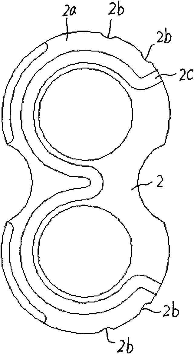
[0022] see Figure 1a , The back of the side plate 2 is divided into a high-pressure side and a low-pressure side by a sealing ring groove 2c.

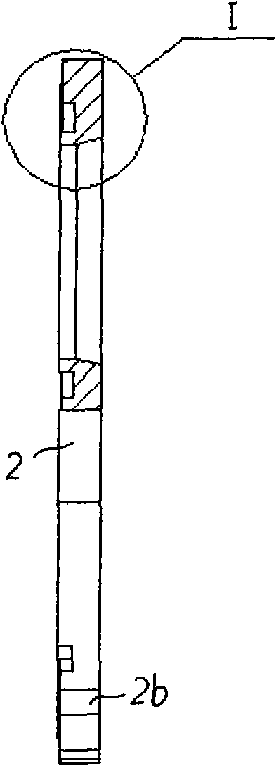
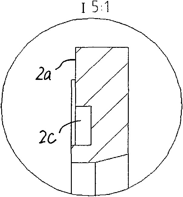
[0023] see Figure 1b , Figure 1c , the structural setting in this embodiment is to arrange a pressure equalizing groove 2a on the surface of the high pressure side of the back of the side plate; The pressure introduction groove 2b connected with the groove 2a, Figure 1a As shown, in this embodiment, there are four pressure-inducing grooves 2b at different circumferential positions in the low-pressure area, and the pressure-introducing grooves 2b guide the high-pressure oil on the back of the side plate to the low-pressure area of ​​the gear oil pump; the outer periphery of the front side plate has no chamfers right angle form.

[0024] see Figure 1d , the structural setting in this embodiment makes the hydraulic thrust f2 on the back of the side plate relative to Figure 3c The hydraulic thrust f2 on the back side of the exi...


PUM


Abstract

The invention discloses a constant pressure full-balanced type floating side plate, the back of which is separated into a high pressure side and a low pressure side by a sealing ring groove. The floating side plate is characterized in that the surface of the high pressure side at the back of the side plate is provided with a pressure equalizing groove; a pressure guide groove which is used for leading high pressure oil at the back of the side plate into a low pressure area of a gear oil pump and is communicated with the pressure equalizing groove is arranged at a low pressure area of the circumference surface of the side plate along the axial direction; the periphery outside the front of the side plate is a right-angle form without chamfer angle. The invention can effectively improve the performance and the reliability of the gear oil pump and prolong the service life thereof.

Description

technical field [0001] The invention relates to a side plate of a gear oil pump, more specifically a high-pressure, high-speed, high-impact hydraulic gear oil pump side plate used as a power element of a hydraulic system. Background technique [0002] As the power component of the hydraulic system, the gear oil pump is widely used in the hydraulic system of construction machinery such as forklifts, loaders, excavators, and cranes. Because of its simple structure, small size, light weight, strong self-priming ability, and insensitivity to oil pollution, it is widely used in the field of hydraulic technology, especially in the construction machinery industry. However, the unbalanced radial hydraulic pressure, short bearing life, and low overall efficiency seriously restrict the development and wider promotion of gear oil pumps. With the wide application and improvement of hydraulic technology, energy saving and environmental protection will be the mainstream design concept of...

Claims


Application Information

Patent Timeline
Patent Type & Authority Applications(China)
IPC IPC(8): F04C15/00
Inventor 郑金朝陈文辉杨永彬孙小平
Owner HEFEI CHANGYUAN HYDRAULICS
Why Eureka
Try Eureka