Overload valve

An overload valve and valve seat technology, applied in fluid pressure actuating devices, servo motor components, mechanical equipment, etc., can solve the problems of poor reliability and short service life of overload valves.

Active Publication Date: 2012-10-17
浙江高宇液压机电有限公司
View PDF10 Cites 4 Cited by
  • Summary
  • Abstract
  • Description
  • Claims
  • Application Information

AI Technical Summary

Problems solved by technology

[0005] The purpose of the present invention is to provide an overload valve to solve

Method used


Image

  • Overload valve
  • Overload valve

Examples


Embodiment Construction

[0040] In order to further explain the technical solution of the present invention, the present invention will be described in detail below through specific examples.

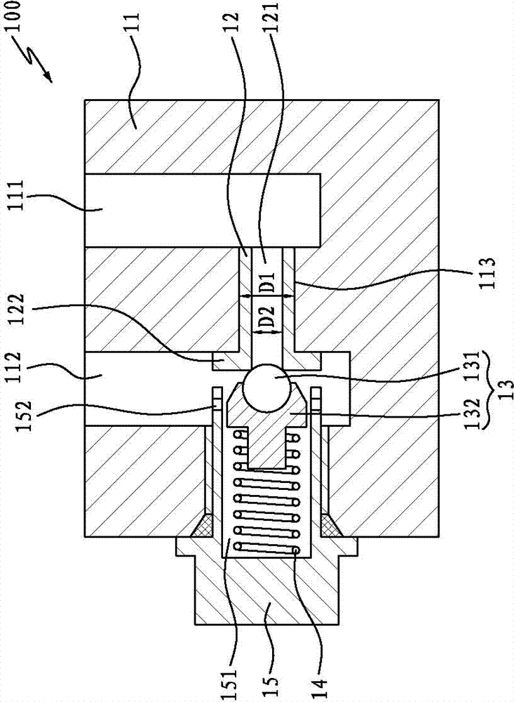
[0041] Such as figure 1 As shown, it is the first embodiment of an overload valve related to the present invention, which is a one-way overload valve 100. The one-way overload valve 100 includes a valve body 11, a valve seat 12, a valve core 13 and a spring 14. The valve The body 11 is provided with an oil inlet chamber 111, an oil return chamber 112 and a valve seat hole 113. The valve seat 12 is movably nested in the valve seat hole 113 and has a first movable stroke. The valve seat 12 has an oil inlet hole 121. The oil inlet hole 121 is used to communicate with the oil inlet chamber 111 and the oil return chamber 112, and the diameter D1 of the valve seat hole 113 is larger than the inner diameter D2 of the contact port between the valve seat oil inlet hole 121 and the valve core 13; the spring 14 is against...


PUM


Abstract

The invention discloses an overload valve, which comprises a valve body, a valve seat, a valve core and a spring, wherein an oil inlet cavity, an oil return cavity and a valve seat hole are arranged on the valve body; the valve seat is movably sleeved inside the valve seat hole and has a first moving stroke; the valve seat comprises an oil inlet hole communicated with the oil inlet cavity and the oil return cavity; and the spring props against the valve core and can drive the valve core to prop against the valve seat so as to block the oil inlet hole; the valve core has a second moving stroke, and the length of the second moving stroke is greater than that of the first moving stroke. Compared with the prior art, the overload valve is simple in structure, small in spring compression and not easy to generate fatigue damage; the impact of the valve core on the valve seat is relatively small when the overload valve is closed; abrasion of the valve core and the valve seat are greatly reduced, and the reliability and the service life of the overload valve can be greatly improved.

Description

technical field [0001] The invention relates to the field of valve body structure, and more specifically relates to an overload valve, which has the characteristics of high reliability and long service life. Background technique [0002] Overload valves are generally used in hydraulic equipment, and mainly play the role of constant pressure relief, pressure stabilization, system unloading and safety protection. At present, the existing overload valves all at least include a valve body, a valve seat, a valve core and a spring. An oil inlet chamber and an oil return chamber are formed on the valve body, an oil inlet hole is formed on the valve seat, and the oil inlet hole It is connected to the oil inlet chamber and the oil return chamber, and the valve core is in conflict with the spring; under normal conditions, under the action of the spring, the valve core will be tightly against the valve seat, so that the oil inlet chamber and the oil return chamber When the pressure in...

Claims


Application Information

Patent Timeline
IPC IPC(8): F15B13/02
Inventor 严光贤
Owner 浙江高宇液压机电有限公司
Why Eureka
Try Eureka