Multifunctional arch support trolley and erection method for multiple arch supports

A multi-functional, arched technology, applied in mining equipment, earth-moving drilling, wellbore lining, etc., can solve the problems of inability to cooperate with mechanized on-site construction of arches, heavy steel arches, and more labor.

Pending Publication Date: 2019-03-29
SICHUAN LANHAI ENG EQUIP MFG CO LTD
View PDF12 Cites 25 Cited by
  • Summary
  • Abstract
  • Description
  • Claims
  • Application Information

AI Technical Summary

Problems solved by technology

[0003] At present, in the process of tunnel construction, steel arches need to be erected on the excavated rock face. The traditional steel arches are heavy, and the installation of the arches is mainly carried out by manpower. It has the following disadvantages: 1. The number of workers required is large, and the labor intensity Large size and low efficiency. Existing arch frames are mostly connected by flanges and sleeves. When on-site installation requires a lot of manual construction; 2. Existing arch frames cannot match the mechanized on-site construction of arch frames
[0004] In order to solve the problems existing in the steel arches in the prior art, manipulators have gradually appeared in the arching operation, but the current manipulators use the steel arch clamping equipment to hold several sections of the steel arch at the same time, and then Fixed connections such as welding are performed on the joints. Such operations also require more labor, and the safety cannot be guaranteed.
Therefore, with the development and progress of technology, foldable steel arches have gradually appeared. After the steel arches are installed and folded, they are transported to the tunnel for unfolding and erection operations, leaving a lot of operations on the steel arches. Outside the tunnel, it solves the time-consuming and labor-consuming problems of erecting steel arches in the existing tunnel construction

Method used


Image

  • Multifunctional arch support trolley and erection method for multiple arch supports
  • Multifunctional arch support trolley and erection method for multiple arch supports
  • Multifunctional arch support trolley and erection method for multiple arch supports

Examples


Embodiment 2

[0059] A method for erecting a multi-arch arch, using the multi-functional arch trolley in Embodiment 1 to erect a multi-arch arch, comprising the following steps:

[0060] Step 1: Make a multi-arch frame: Arrange two or more folded arch frames in parallel, and then connect them with several strengthening connecting rods to form a multi-arch frame;

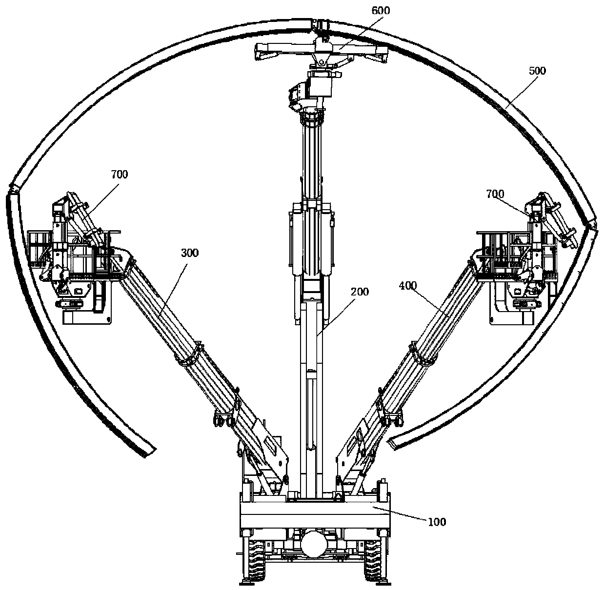
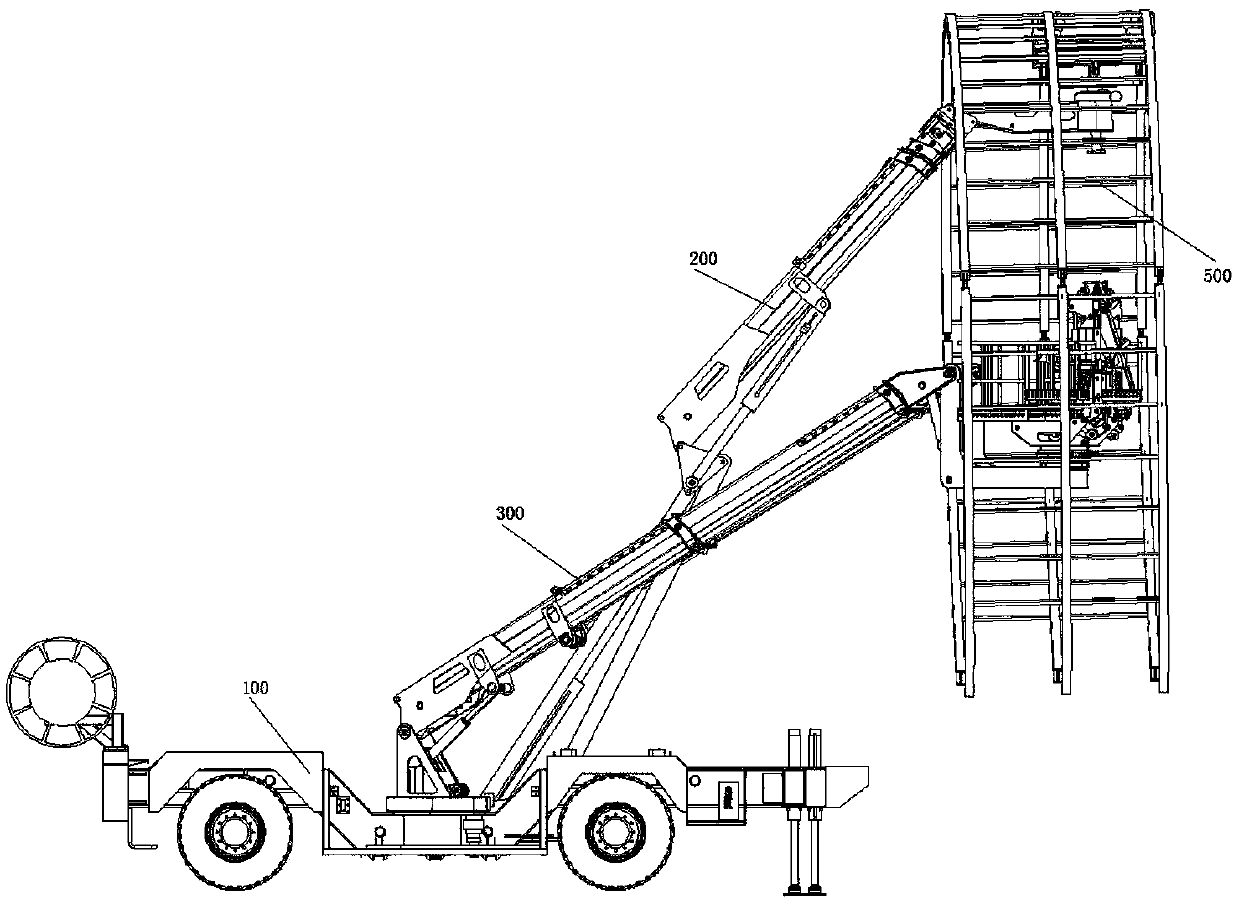
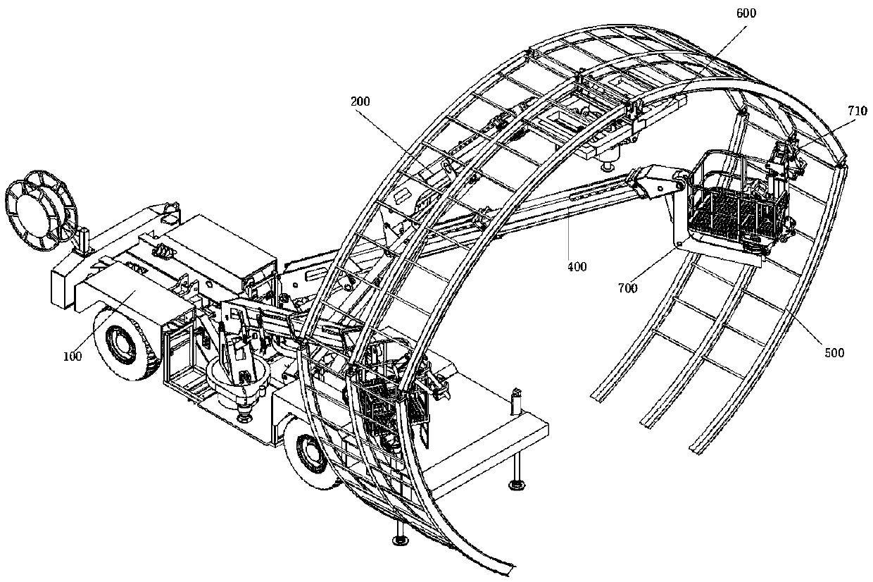
[0061] Step 2: Fold the multiple arches on the support fixture 600: place the support fixture 600 under the top arch section, and control the support fixture 600 to lift the top arch section to a certain height through the main arm frame 200. The left arch section and the right arch section are symmetrically folded towards the inner side of the top arch section; when the support fixture 600 is slowly lowered through the main boom 200, the left arch section and the right arch section gradually move toward the top arch section. The inner side of the arch is folded until the folding of the multi-arch arch frame is completed; the left...


PUM


Abstract

The invention belongs to the field of tunnel construction, and discloses a multifunctional arch support trolley. The trolley comprises a trolley body. A main arm frame, a right auxiliary arm frame anda left auxiliary arm frame which the rotation and stretchable functions are arranged on the trolley body. The main arm frame is located between the right auxiliary arm frame and the left auxiliary arm frame. A support clamp for clamping / supporting arch supports is arranged at the end of the main arm frame, and a rotation mechanism is arranged in the support clamp so as to control the arch supports to rotate; the ends of the right auxiliary arm frame and the left auxiliary arm frame are each provided with a worker operation platform. The multifunctional arch support trolley can transport folded steel arch supports into the tunnel stably, and perform direct changes inside the tunnel, meanwhile after the arch supports are transported to a preset place inside the tunnel, the folded steel archsupports can be safely, rapidly and stably lifted to the preset height, and the operation requirement for multi-step long-distance lifting is met.

Description

technical field [0001] The invention relates to the technical field of tunnel construction, in particular to a tunnel arch erection device. Background technique [0002] In recent years, my country's underground engineering has developed rapidly, and mechanized operations have gradually been widely used in engineering technology, especially in the field of underground tunnel construction. [0003] At present, in the process of tunnel construction, steel arches need to be erected on the excavated rock face. The traditional steel arches are heavy, and the installation of the arches is mainly carried out by manpower. It has the following disadvantages: 1. The number of workers required is large, and the labor intensity Large size and low efficiency. Existing arches are mostly connected by flanges and sleeves. When on-site installation requires a lot of manual construction; 2. Existing arch constructions cannot cooperate with mechanized on-site construction of arches. [0004] ...

Claims


Application Information

Patent Timeline
Patent Type & Authority Applications(China)
IPC IPC(8): E21D11/18E21D11/40
CPCE21D11/18E21D11/40
Inventor 兰冰邱章令
Owner SICHUAN LANHAI ENG EQUIP MFG CO LTD
Why Eureka
Try Eureka