Main steam door switch in-place feedback structure

A main steam valve and switch technology, which is applied in the direction of engine components, machines/engines, mechanical equipment, etc., can solve time-consuming and labor-intensive problems, achieve the effects of prolonging service life, avoiding false sending of main steam valve closing signals, and flexible adjustment

Pending Publication Date: 2019-03-29
福建华电可门发电有限公司
View PDF0 Cites 2 Cited by
  • Summary
  • Abstract
  • Description
  • Claims
  • Application Information

AI Technical Summary

Problems solved by technology

[0004] Aiming at the deficiencies of the prior art, the present invention provides a main valve switch in-position feedback structure, which solves the time-consuming and laborious problems of adjusting the installation position of the travel switch and re-drilling for positioning after each maintenance

Method used


Image

  • Main steam door switch in-place feedback structure
  • Main steam door switch in-place feedback structure
  • Main steam door switch in-place feedback structure

Examples


Embodiment Construction

[0018] The following will clearly and completely describe the technical solutions in the embodiments of the present invention with reference to the accompanying drawings in the embodiments of the present invention. Obviously, the described embodiments are only some, not all, embodiments of the present invention. Based on the embodiments of the present invention, all other embodiments obtained by persons of ordinary skill in the art without making creative efforts belong to the protection scope of the present invention.

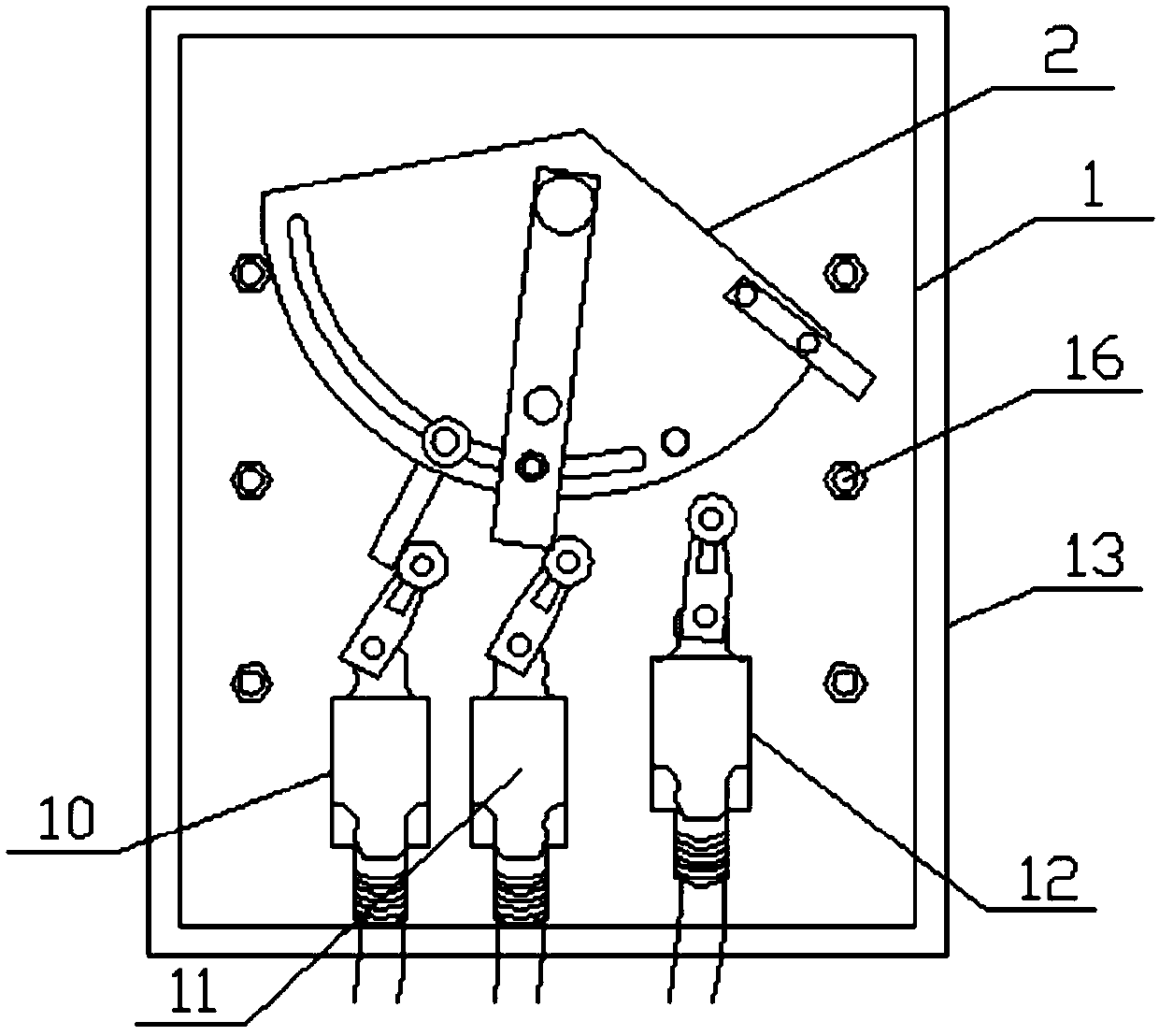
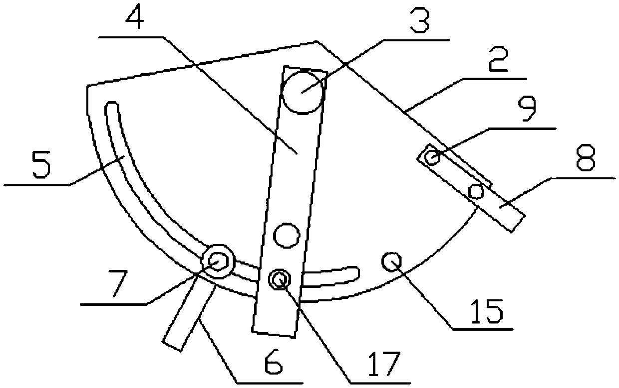
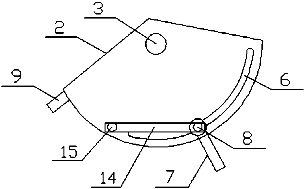
[0019] see Figure 1-3 , the present invention provides a technical solution: a main valve switch position feedback structure, including a mounting plate 1, the upper end of the front face of the mounting plate 1 is provided with a movable plate 2, and the position of the middle part of the upper end of the movable plate 2 passes through the first connecting piece 3 is connected with the installation plate 1 in rotation, the position of the middle part of the ...


PUM


Abstract

The invention discloses a main steam door switch in-place feedback structure. The main steam door switch in-place feedback structure comprises a mounting plate, wherein the middle of the upper end ofa movable plate is rotationally connected with the mounting plate through a first connecting part, a first stirring plate is arranged in the middle of the movable plate, an arc-shaped groove is formedin the left side of the lower edge of the movable plate, a second stirring plate is arranged on the left side of the lower end of the movable plate, the upper end of the second stirring plate is movably connected with the arc-shaped groove through a second connecting part, a third stirring plate is arranged at the right end of the lower edge of the movable plate, a first turn-off travel switch isarranged on the left side of the lower end of the mounting plate, a second switch in-place travel switch is arranged on the right side of the first turn-off travel switch, and the right side of a second turn-off travel switch is provided with an open-to-place travel switch. The invention relates to the technical field of protection of steam turbine generators of power plants. According to the main steam door switch in-place feedback structure, the purpose of not needing to be re-punched and positioned is achieved, and the installation position of the travel switch needs to be adjusted after being overhauled for each time.

Description

technical field [0001] The invention relates to the technical field of turbine generator protection in a power plant, in particular to a main steam valve switch in-position feedback structure. Background technique [0002] When the unit is in normal operation, when some important parameters exceed the limit, it will send the main steam valve of the steam turbine to close the signal to trip the unit. Large-scale units are generally equipped with one limit switch for opening and two limit switches for closing. When the main steam valve is normally closed, it is best to send out two signals for closing the main valve at the same time. However, the existing design needs to be adjusted after each maintenance. The installation position of the travel switch is such that the main steam valve switch is in place and the travel switch operates normally. After the debugging is normal, the travel switch needs to be re-drilled and positioned, which is time-consuming and laborious. Conte...

Claims


Application Information

Patent Timeline
Patent Type & Authority Applications(China)
IPC IPC(8): F01D21/00F01D17/10
CPCF01D21/003F01D17/10
Inventor 何宗源
Owner 福建华电可门发电有限公司
Why Eureka
Try Eureka