
Assembly method of minitype non-standard rolling bearing

A technology of rolling bearings and assembly methods, which is applied in the direction of bearing components, shafts, bearings, mechanical equipment, etc., can solve problems such as skew, part has been completely pressed in, part has not been pressed in, press-fitting efficiency is low, stuck, etc., to achieve Improved rotation flexibility, strong pertinence, and simple assembly methods

Active Publication Date: 2019-03-29
LUOYANG BEARING RES INST CO LTD
View PDF7 Cites 0 Cited by
  • Summary
  • Abstract
  • Description
  • Claims
  • Application Information

AI Technical Summary

Problems solved by technology

This method has the following disadvantages: (1) In the process of pressing down from top to bottom, skewing occurs due to the unevenness of the force. Some parts have been completely pressed in, and some have not yet been pressed in. Only when the pressed part is re-pressed can the crown cage be fully assembled as a whole, and the press-fitting efficiency is low; (2), due to the skewing of the bearing during the pressure application process, the crown cage will be deformed to a certain extent Deformation, and the crown-shaped cage is very close to the inner and outer rings of the bearing. A considerable proportion of bearings are deformed due to the crown-shaped cage, which leads to unqualified rotation flexibility of the bearing after assembly, and pauses and stagnation during rotation; (3) For bearings with unqualified rotation flexibility, the crown-shaped cage needs to be removed, which wastes a lot of manpower and material resources

Method used


Image

  • Assembly method of minitype non-standard rolling bearing
  • Assembly method of minitype non-standard rolling bearing
  • Assembly method of minitype non-standard rolling bearing

Examples


Embodiment Construction

[0027] Terms such as "upper", "lower", "left", "right", "middle" and "one" quoted in this specification are only for the convenience of description and are not used to limit the scope of the present invention. The scope of implementation and the change or adjustment of its relative relationship shall also be regarded as the scope of implementation of the present invention without substantive changes in technical content.

[0028] In the miniature non-standard rolling bearing assembled in the present invention, the height of the inner ring is higher than that of the outer ring, and the total height of the crown-shaped cage is basically the same as that of the outer ring of the bearing.

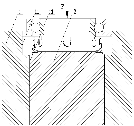
[0029] Please refer to image 3 , image 3 It is a schematic diagram of the assembly method of the miniature non-standard rolling bearing provided by the present invention.

[0030] The invention provides a method for assembling miniature non-standard rolling bearings. The assembling method i...


PUM


Abstract

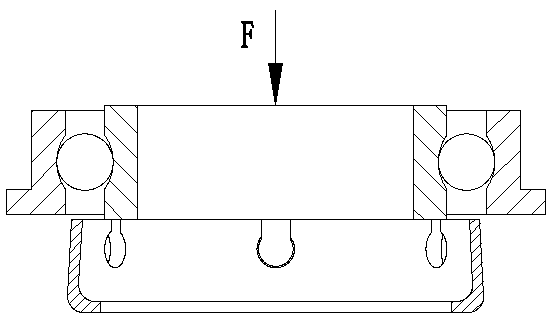
The invention discloses an assembly method of a minitype non-standard rolling bearing. Assembly of the minitype non-standard rolling bearing is completed on an auxiliary assembly device which comprises a positioning base. A groove for positioning the outer ring of the bearing is formed in the upper portion of the positioning base. An inner pillar of a boss on the upper portion of the center of thepositioning base is in interference fit with the positioning base. The outer circumference face of the boss fits with a crown cage in internal diameter so that the boss can support the crown cage. The assembly method comprises the steps that the inner ring of the bearing, steel balls and the outer ring of the bearing are assembled into a semi-finished product; the crown cage is disposed on the boss, and the boss positions the crown cage from the inside of the crown cage; the semi-finished product is disposed above the crown cage, the outer ring of the bearing is in clearance fit with the inner wall of the groove; the steel balls are divided through a division ball so that each steel ball is located at a pocket locking notch of the crown cage; and the semi-finished product is pressed fromtop to bottom to complete assembly. The bearing and the crown cage are prevented from moving during assembly, it can be ensured that the crown cage does not deform, and rotation flexibility of the bearing is not affected.

Description

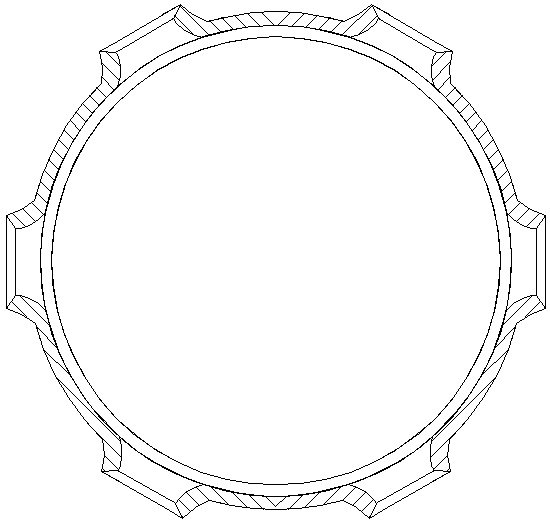
technical field [0001] The invention relates to the technical field of rolling bearing assembly, in particular to a method for assembling a miniature non-standard rolling bearing. Background technique [0002] The miniature non-standard rolling bearing in the present invention refers to a miniature rolling bearing whose inner ring is higher than the outer ring. The crown-shaped cage made of stainless steel plate used in miniature non-standard rolling bearings, if necessary, needs to be surface treated to improve strength and ensure that no distortion occurs during assembly. The ball pocket has a smooth contact surface with the steel ball after being pressed, so the starting torque Or the low-speed friction torque is small, the cage strength is high, and the speed range is wide, up to 50000r / min. [0003] The shape of the crown cage of the miniature non-standard rolling bearing to be assembled in the present invention is as follows: figure 1 shown. The distance in the diam...

Claims


Application Information

Patent Timeline
Patent Type & Authority Applications(China)
IPC IPC(8): F16C43/06
CPCF16C43/06
Inventor 张风琴刘艳娜焦叶凡张旭魏秀君宋相霖
Owner LUOYANG BEARING RES INST CO LTD
Learn More