Lamp stroboscopic dimming device and using method thereof

A technology for stroboscopic dimming devices and lamps, which is applied to lighting devices, lighting device parts, electric light sources, etc., can solve the problems of large size and long length of lamps, and achieve the effect of uniform light and better switching effect.

Pending Publication Date: 2019-03-29
PR LIGHTING
View PDF0 Cites 0 Cited by
  • Summary
  • Abstract
  • Description
  • Claims
  • Application Information

AI Technical Summary

Problems solved by technology

[0003] However, when it is necessary to adjust the light strobe and light intensity, the existing structure is mostly divided into two independent devices to realize, one is the device for realizing the stroboscopic effect, and the other is the device for realizing the dimming effect. The target function is achieved, but due to the two independent devices, the assembled lamps are larger in size and longer in length, so there are obvious deficiencies

Method used


Image

  • Lamp stroboscopic dimming device and using method thereof
  • Lamp stroboscopic dimming device and using method thereof
  • Lamp stroboscopic dimming device and using method thereof

Examples


Embodiment Construction

[0039] Embodiments of the present invention will be described in detail below.

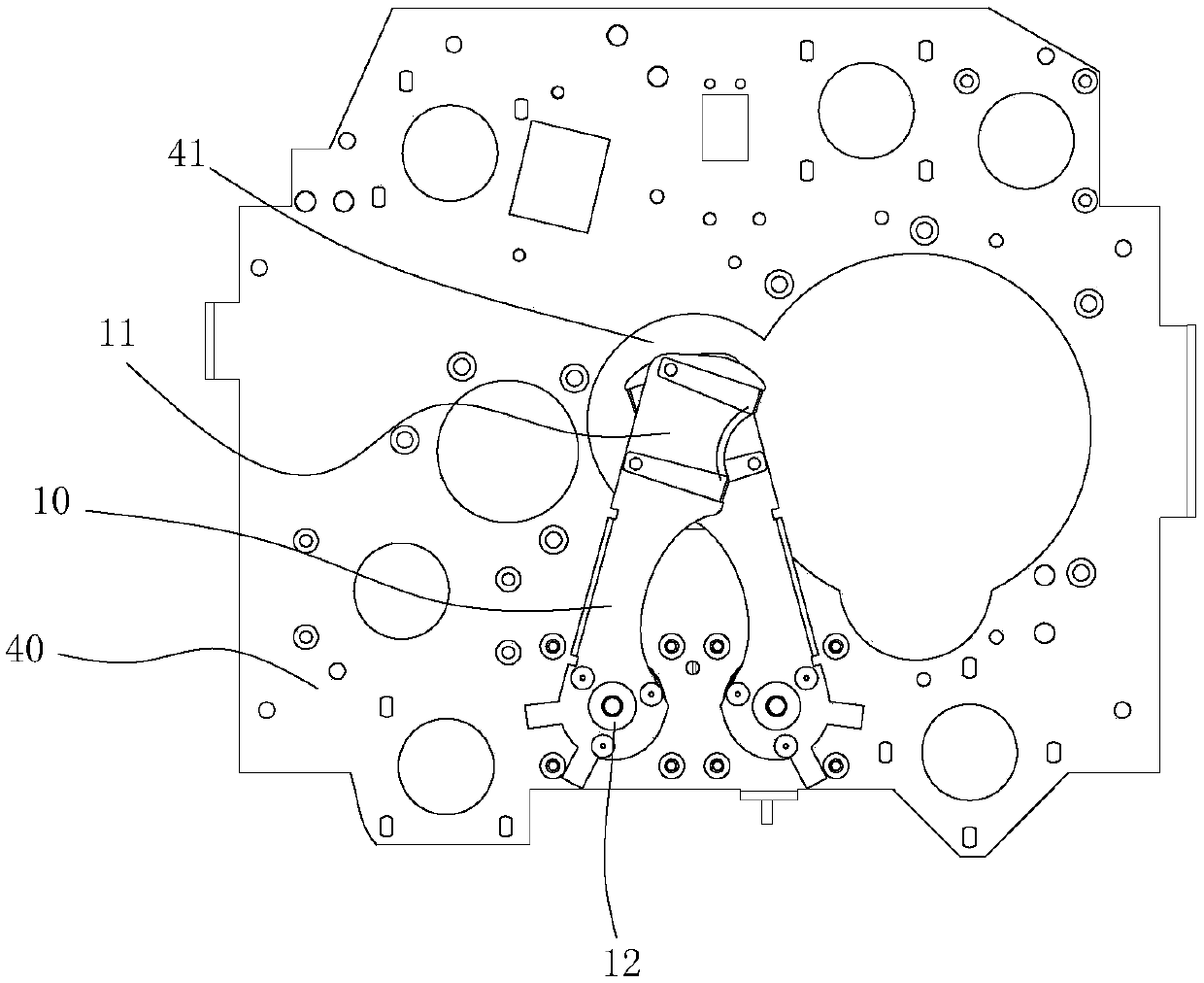
[0040] image 3 and Figure 4 The middle dotted line indicates the position of the light hole 41 .

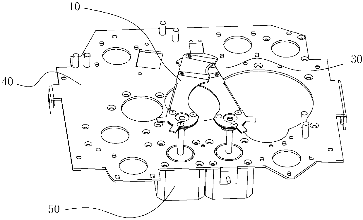
[0041] Such as Figure 1 to Figure 4 As shown, the strobe dimming device for lamps includes a dimmer 10, a diffuser 30 and a mounting frame 40, the dimmer 10 is installed on the mounting frame 40, and the dimmer 10 is provided with a dimming end 11 and a driving end 12, the dimming end 11 is provided with an embedding position 111, the embedding position 111 is installed with the flexible light sheet 30, the driving end 12 is connected with a driving mechanism 50, and the driving mechanism 50 The dimmer sheet 10 is driven to move; the installation frame 40 is at least provided with an optical hole 41 , and the dimmer terminal 11 is arranged above the optical hole 41 .

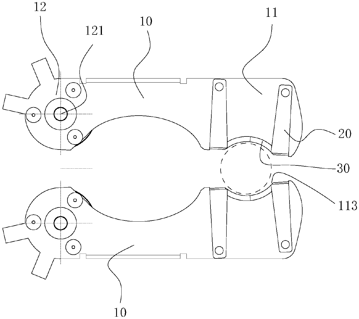
[0042] Such as Figure 5 As shown, the side of the dimming end 11 close to the light hole 41 is an incision surface 113, and ...


PUM


Abstract

The invention discloses a lamp stroboscopic dimming device and a using method thereof. The lamp stroboscopic dimming device comprises a dimming sheet, a soft light sheet and a mounting frame, whereinthe dimming sheet is mounted on the mounting frame, the dimming sheet is provided with a dimming end and a driving end, an embedded end is arranged at the dimming end, the embedded position is provided with the soft light sheet, the driving end is connected with a driving mechanism, and the driving mechanism drives the dimming sheet to move; the mounting frame is at least provided with a light hole, and the dimming end is arranged above the light hole. The arrangement of the soft light sheet achieves that one device achieves two working effects of stroboflash and dimming.

Description

technical field [0001] The invention relates to a lamp, in particular to a lamp stroboscopic dimming device and an application method thereof. Background technique [0002] Luminaires refer to appliances that can transmit light, distribute and change the light distribution of the light source, including all parts required to fix and protect the light source except the light source, as well as the necessary line accessories for connection to the power supply. With the continuous development of science and technology, lamps and lanterns have been widely used in various fields. The styles are also varied. [0003] However, when it is necessary to adjust the light strobe and light intensity, most of the existing structures are realized by two independent devices, one is the device for realizing the stroboscopic effect, and the other is the device for realizing the dimming effect. The target function is realized, but since there are two independent devices, the assembled lamps ...

Claims


Application Information

Patent Timeline
IPC IPC(8): F21S10/06F21V14/00
CPCF21S10/06F21V14/006
Inventor 冯圣勋
Owner PR LIGHTING
Why Eureka
Try Eureka