Filing cabinet dolly

a filing cabinet and dolly technology, applied in the field of filing cabinet dolly, can solve the problems of affecting the stability of the filing cabinet, so as to achieve the effect of stable support for the filing cabin

Active Publication Date: 2008-01-17
DESBIENS BENOIT
View PDF10 Cites 8 Cited by
  • Summary
  • Abstract
  • Description
  • Claims
  • Application Information

AI Technical Summary

Benefits of technology

[0007]An advantage of the present invention is that the dolly is so formed as to accommodate the longest width dimension of the cabinet across the breadth of the dolly when presented to the front of the cabinet.
[0008]Another advantage of the present invention is that the dolly provides a platform of significant extent to afford a stable support for the filing cabinet.
[0009]A further advantage of the present invention is that the platform of the dolly has an elevating mechanism to lift the cabinet out of contact with the floor to give more than adequate clearance to achieve ease of movement.
[0010]Yet a further advantage of the present invention is that the platform of the dolly, when in the elevated position, is still low enough to simply allow the filing cabinet to simply abut onto the floor thus prevent the

Problems solved by technology

It is well known that considerable difficulty is encountered when attempting to reposition a filing cabinet, particularly once it has some contents, in view of its cumbersome nature which is aggravated by the absence of any real handholds for maneuvering the cabinet from one place to another and emplacing it correctly at its new location.
Especial difficulty is experienced when moving lateral filing cabinets which can easily twist and deform during manhandling thereby potentially causing damage or at least compromising structu

Method used


Image

  • Filing cabinet dolly
  • Filing cabinet dolly
  • Filing cabinet dolly

Examples


Embodiment Construction

[0025]With reference to the annexed drawings the preferred embodiment of the present invention will be herein described for indicative purpose and by no means as of limitation.

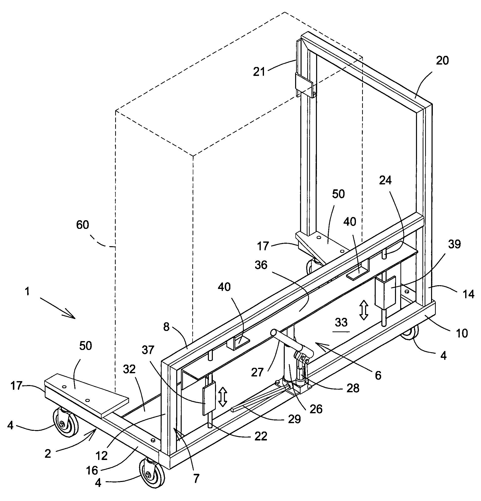
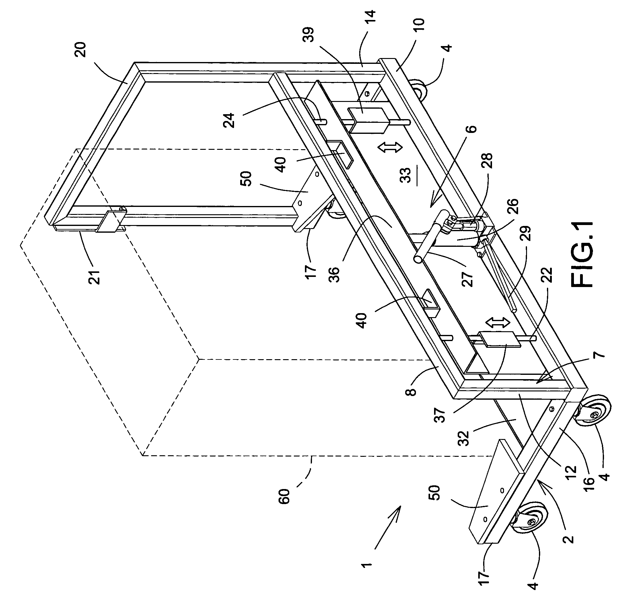
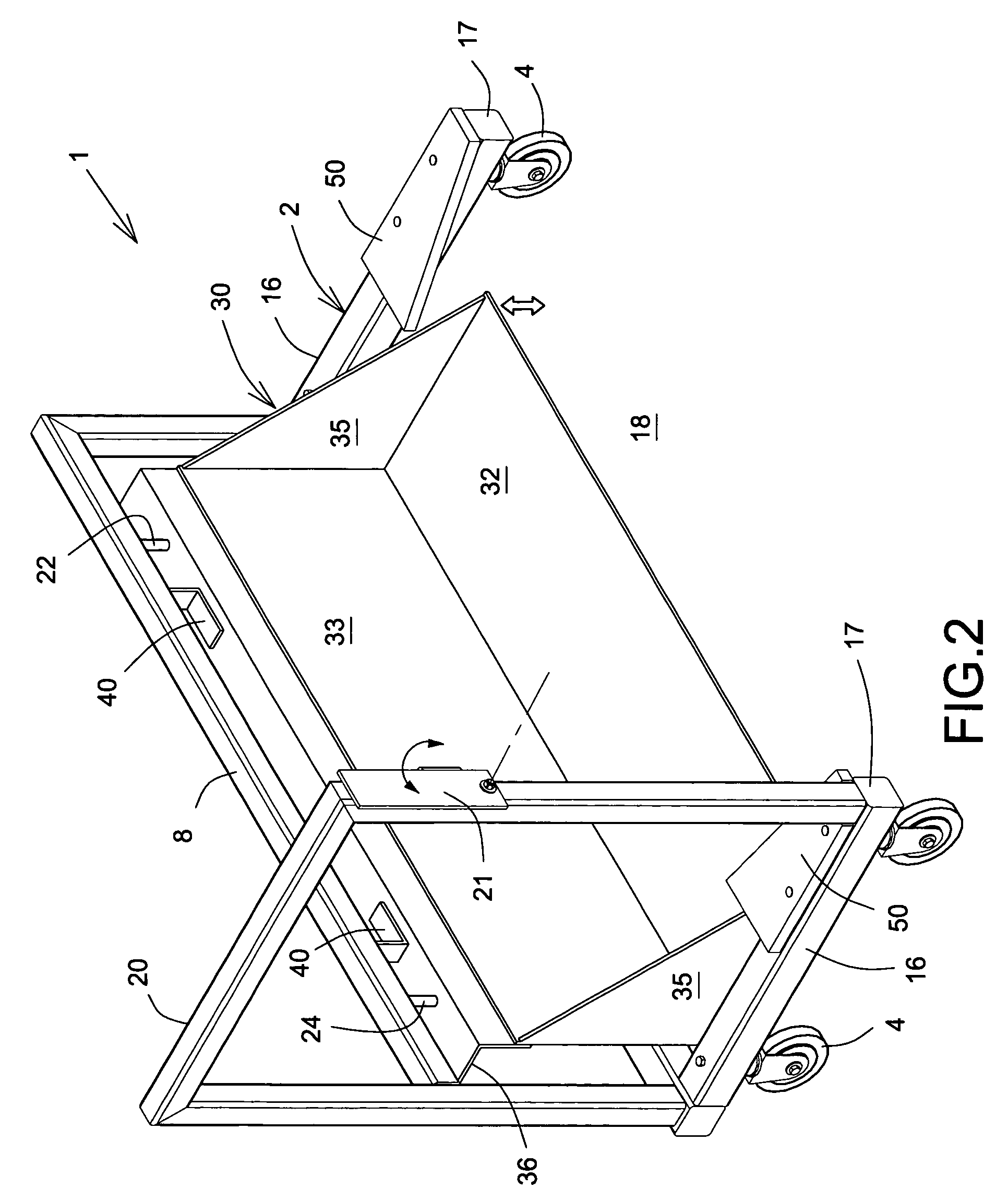
[0026]Referring to the drawings there is shown generally at 1 a filing cabinet dolly in accordance with an embodiment of the present invention comprising a mobile wheeled framework 2 provided with four casters 4 at each of four corners. The framework 2 is constructed of lightweight metal, for example aluminum, and is formed of hollow square section tubing suitably welded at appropriate joints.

[0027]The framework 2 has a closed rear end 6 comprising a rectangular structure 7 with two spaced apart horizontal rails 8, 10 and two side limbs 12, 14 bridging each of the rails at their ends. Side bars 16 extend orthogonally from the relatively lower rail 10 at each end of the rectangular structure terminating in free ends 17 between which is defined an open front end 18. The casters 4 are mounted on the underside of ...


PUM


Abstract

A filing cabinet dolly provides a wheeled framework within and upon which a filing cabinet may be disposed for transport, the framework including a vertically power-assisted movable platform for accommodating the cabinet in a stable orientation.

Description

FIELD OF THE INVENTION[0001]The present invention relates to a filing cabinet dolly of the kind employed to facilitate moving the cabinet either with contents or without from one location to another.BACKGROUND OF THE INVENTION[0002]It is well known that considerable difficulty is encountered when attempting to reposition a filing cabinet, particularly once it has some contents, in view of its cumbersome nature which is aggravated by the absence of any real handholds for maneuvering the cabinet from one place to another and emplacing it correctly at its new location. Especial difficulty is experienced when moving lateral filing cabinets which can easily twist and deform during manhandling thereby potentially causing damage or at least compromising structural integrity.[0003]It is well known to use what is commonly known as a dolly consisting of a small wheeled platform provided with an appropriate handle giving sufficient leverage and mechanical advantage to enable an operator to loa...

Claims


Application Information

Patent Timeline
IPC IPC(8): B62B5/00
CPCB62B3/002B62B3/0612B62B3/0643B62B2203/70B62B2203/07B62B2203/10B62B2202/30
Inventor DESBIENS, BENOIT
Owner DESBIENS BENOIT
Why Eureka
Try Eureka