Lighting device and lighting system

A technology for lighting devices and light-emitting parts, which can be applied to lighting devices, energy-saving lighting, electric lamp circuit layout, etc., and can solve the problems of changing the color temperature of light emission and not having a phase control device, etc.

Inactive Publication Date: 2012-11-28
PANASONIC INTELLECTUAL PROPERTY MANAGEMENT CO LTD
View PDF5 Cites 8 Cited by
  • Summary
  • Abstract
  • Description
  • Claims
  • Application Information

AI Technical Summary

Problems solved by technology

[0009] However, the lighting device in Non-Patent Document 1 adopts a method of adjusting the light by changing the setting of the current value in the constant current control, so it is not assumed that the phase control device is used for light adjustment.
In addition, although the phase control device can be applied to the lighting device of Patent Document 1, the color temperature of the light emission color cannot be changed according to the dimming level.

Method used


Image

  • Lighting device and lighting system
  • Lighting device and lighting system
  • Lighting device and lighting system

Examples


no. 1 Embodiment approach )

[0034] figure 1 It is a partially cutaway view showing a schematic configuration of the bulb-type lighting device in the first embodiment of the present invention.

[0035] The lighting device 1 has an appearance shape similar to that of an incandescent bulb. The cylindrical casing 2 is formed of insulating material such as resin, and an E-shaped lamp cap 3 is provided at one end thereof, and a disc-shaped heat sink 5 is provided at the other end. A lighting device 4 is accommodated in an inner space of the housing 2 closed by the base 3 and the heat sink 5 . A light emitting module 6 is mounted on the surface of the heat sink 5 opposite to the case sealing surface, and a globe 7 covering the light emitting module 6 is attached.

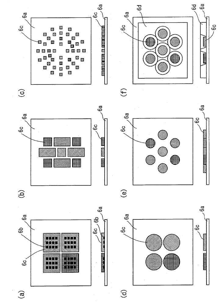
[0036] The light emitting module 6 is formed by disposing a wiring pattern on the surface of the substrate 6a, mounting the LED chip 6b on the wiring pattern, and wrapping the LED chip 6b with the resin molding member 6c. The resin molding member ...

no. 2 Embodiment approach )

[0063] Figure 4 It is a circuit diagram showing the structure of the lighting circuit in 2nd Embodiment of this invention.

[0064] In the first embodiment, the LED array is turned on with direct current, but in the second embodiment, the LED array is turned on with alternating current. Therefore, in the second embodiment, a rectification circuit is provided instead of a rectification smoothing circuit. In addition, to adapt to the AC lighting, the structure of the LED array has changed. Other configurations are the same as those of the first embodiment.

[0065] In the LED array, 8 groups of LED1 to LED8, a total of 46 LEDs are connected in series. The number and color temperature of LEDs included in each group are as follows.

[0066] LED1: 9, 2800[K]

[0067] LED2: 8, 2800[K]

[0068] LED3: 8, 3500[K]

[0069] LED4: 7, 3500[K]

[0070] LED5: 6, 5000[K]

[0071] LED6: 4, 5000[K]

[0072] LED7: 3, 6700[K]

[0073] LED8: 1, 6700[K]

[0074] The total number N [pie...

no. 3 Embodiment approach )

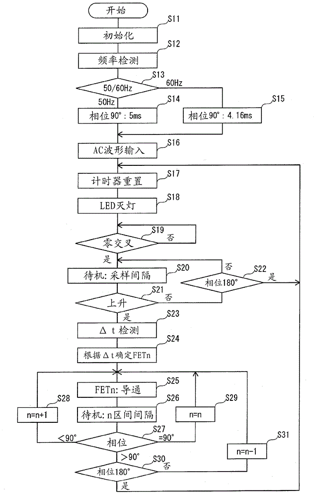
[0096] In the third embodiment, the elapsed time from the zero cross of the AC voltage is handled as information indicating the voltage supplied to the LED array. The circuit configuration itself of the lighting circuit is the same as that of the second embodiment, but the operation of the microcomputer 12 is different from that of the second embodiment.

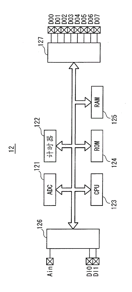
[0097] Figure 9 The internal structure of the microcomputer 12 is shown. The microcomputer 12 has an analog-to-digital converter 121 , a timer 122 , a CPU 123 , a ROM 124 , a RAM 125 , an input port 126 , and an output port 127 . The input port 126 is provided with an analog input terminal Ain, and digital input terminals DI0 and DI1. Digital output terminals DO0 to DO7 are provided on the output port 127 . CPU123 operates according to the program and data stored in ROM124 and RAM125.

[0098] Figure 10 A table indicating the voltage phase of the AC power supply, the number of the switching element turned on, and the ...


PUM


Abstract

Provided is a lighting device which can be dimmed and subjected to change in color temperature of the color of emitted light in accordance with a dimming level. To the lighting device, alternating-current power that is phase-controlled is supplied. The lighting device is provided with a light-emitting-part array and a switching means. The light-emitting-part array is constituted of a plurality of light-emitting parts, which are two or more kinds of light-emitting parts having different colors of emitted light. The switching means switches an electrical connection relationship between the light-emitting parts included in the light-emitting-part array so as to change a ratio between the number of light-emitting parts inserted in series to an electrical power supply channel and the number of light-emitting parts included therein for each color of emitted light in accordance with a voltage supplied to the light-emitting-part array.

Description

technical field [0001] The present invention relates to a lighting device and a lighting system including light emitting elements such as LEDs (Light Emitting Diodes). Background technique [0002] In recent years, from the perspective of protecting the earth's environment, light-emitting elements such as LEDs have been gradually applied to general lighting. For example, Non-Patent Document 1 discloses a lighting device that uses a rectification and smoothing circuit to convert an AC voltage supplied by a commercial power supply into a DC voltage, and performs constant current control to light the LED array while applying the DC voltage to the LED array. . In addition, Patent Document 1 discloses an AC lighting device that directly applies an AC voltage supplied from a commercial power source to an LED array. [0003] prior art literature [0004] patent documents [0005] Patent Document 1: Special Publication No. 2008-544569 [0006] non-patent literature [0007] No...

Claims


Application Information

Patent Timeline
Patent Type & Authority Applications(China)
IPC IPC(8): H05B37/02H05B44/00
CPCH05B33/0872Y02B20/383Y02B20/19H05B33/0827H05B45/20H05B45/46Y02B20/00Y02B20/30
Inventor 濑户本龙海永井秀男植本隆在
Owner PANASONIC INTELLECTUAL PROPERTY MANAGEMENT CO LTD
Why Eureka
Try Eureka