Building heat collection and removal system based on sky radiation and solar heat collection

A technology of solar heat collection and solar heat collectors, applied in solar heating systems, solar heat collectors, solar heat collector controllers, etc., can solve problems such as difficulty, heat supply, and increased system setup costs, and achieve saving energy, improve comfort, and reduce building energy consumption

Inactive Publication Date: 2019-03-29
HUAZHONG UNIV OF SCI & TECH
View PDF11 Cites 8 Cited by
  • Summary
  • Abstract
  • Description
  • Claims
  • Application Information

AI Technical Summary

Problems solved by technology

[0005] 1. The above-mentioned heat collection and heat removal system cannot realize the function of cooling the room during the day in summer, and cannot realize the function of heating the house at night in winter, which leads to certain limitations in its use;
[0006] 2. The heat collection and heat removal process of the above-mentioned heat collection and heat removal system is often single-acted on the upper room or the lower room. If it is necessary to realize heat collection and heat removal at the same time on the upper and lower floors, it is often necessary to set up two sets of heat collectors corresponding to one room. The heat dissipation system not only greatly increases the installation cost of the heat collection and heat dissipation system, but also affects the lighting in the building;
[0007] 3. The pipe structure of the above-mentioned heat collection and heat removal system is set inside the wall. It is difficult to install the pipes. It often needs to be installed during construction or decoration. The installation is difficult and has certain limitations. It is difficult to maintain and overhaul the heat removal system, which indirectly increases the setup cost of the system;
[0008] 4. The above-mentioned heat collection and heat removal system is installed on the outer wall and inside the wall, which not only needs to use the wall to transfer heat or cold to the room, resulting in energy loss, but also may affect the structural strength of the wall and affect the building. The service life and safety of use may lead to unnecessary losses;
[0009] 5. The above-mentioned heat collection and heat removal system is designed with corresponding opening and closing of various switches. The control of the switches is cumbersome, and the setting of multiple switches also has a certain impact on the stability of the system operation. Once a valve fails or is damaged, it will be It will affect the normal operation of the system. In addition, the above-mentioned heat collection and heat removal system needs to accurately control the vacuum degree inside the system, which has high requirements for the sealing of the system structure and the accuracy of control, which may lead to stability problems during the application process. question
[0010] In view of the above reasons, the existing heat collection and heat dissipation systems have certain structural, functional and stability defects, which cannot fully meet the needs of building energy saving and consumption reduction, and have certain limitations.

Method used


Image

  • Building heat collection and removal system based on sky radiation and solar heat collection
  • Building heat collection and removal system based on sky radiation and solar heat collection
  • Building heat collection and removal system based on sky radiation and solar heat collection

Examples


Embodiment Construction

[0040] In order to make the object, technical solution and advantages of the present invention clearer, the present invention will be further described in detail below in conjunction with the accompanying drawings and embodiments. It should be understood that the specific embodiments described here are only used to explain the present invention, not to limit the present invention.

[0041] In addition, the technical features involved in the various embodiments of the present invention described below can be combined with each other as long as they do not constitute a conflict with each other.

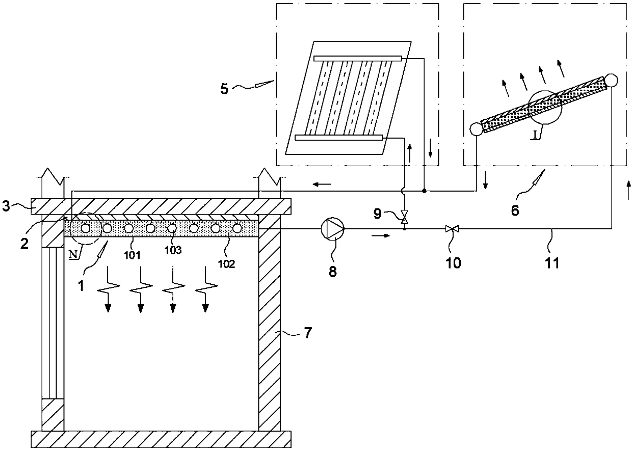
[0042] The overall structural diagram of the house heat collection and heat removal system based on sky radiation and solar heat collection in the preferred embodiment of the present invention is as follows figure 1 As shown in , it includes a double-effect stereotyped phase-change panel 1 arranged on an indoor wall and a solar heat collector 5 and a sky radiation cooler 6 arranged outd...


PUM


Abstract

The invention discloses a building heat collection and removal system based on sky radiation and solar heat collection, and belongs to the field of building energy conservation and renewable energy utilization. A double-effect shaping phase change plate with double-effect shaping phase change working media and capillary tubes, a sky radiation cooler and a solar heat collector are arranged, and thecorresponding operation of heat transfer circulating media in the capillary tubes in summer and winter is utilized, so that the temperature regulating process of cooling indoors all the day in summerand heating indoors all the day in winter is effectively realized. The building heat collection and removal system has the advantages of the simple structure, simplicity and convenience in control, less difficulty in maintenance and overhaul and wide application range and has good popularization and application values, and the cooling process all day and night in summer and the heating process all day and night in winter can be realized at the same time, so that the use of cooling equipment in summer and heating equipment in winter is reduced, the indoor temperature environment of a buildingin summer and winter is effectively improved, energy is saved, the energy consumption is reduced, and the effects of energy conservation and environmental friendliness of the building are achieved.

Description

technical field [0001] The invention belongs to the field of building energy saving and renewable energy utilization, and in particular relates to a house heat collection and heat discharge system based on sky radiation and solar heat collection. Background technique [0002] In recent years, with the continuous improvement of people's living standards, people's requirements for the indoor environment of buildings are also getting higher and higher. The energy consumption of heating and air conditioning accounts for an increasing proportion of the total energy consumption of buildings. In the final energy consumption, the proportion of building energy consumption is also relatively high, and its proportion often reaches more than 30%. In the sub-item of building energy consumption, more than 40% of energy consumption is often required to create a comfortable heat and humidity in the building. surroundings. Therefore, how to reduce the energy consumption of buildings while a...

Claims


Application Information

Patent Timeline
Patent Type & Authority Applications(China)
IPC IPC(8): F24S60/10F24S50/00F25B23/00F25B49/00F28D15/04
CPCF25B23/003F25B49/00F28D15/04Y02B10/20
Inventor 高佳佳严天张源徐新华
Owner HUAZHONG UNIV OF SCI & TECH
Why Eureka
Try Eureka