Mounting and fixing device and mounting method for capacitive gap sensor

A gap sensor and fixing device technology, applied in the direction of using electrical devices, measuring devices, instruments, etc., can solve problems such as irregularity, complex engine structure, and great influence of sensors, so as to ensure stable work, good application prospects, and scope of application wide effect

Inactive Publication Date: 2019-03-29
SHENYANG LIMING AERO-ENGINE GROUP CORPORATION
View PDF4 Cites 2 Cited by
  • Summary
  • Abstract
  • Description
  • Claims
  • Application Information

AI Technical Summary

Problems solved by technology

[0002] Aircraft engine bench clearance measurement is a method used to check the failure of engine rotating parts. Capacitive clearance sensors are mainly used for measurement. However, due to the complex and compact structure of the engine, the space for installing capacitive clearance sensors is very small.

Method used


Image

  • Mounting and fixing device and mounting method for capacitive gap sensor
  • Mounting and fixing device and mounting method for capacitive gap sensor
  • Mounting and fixing device and mounting method for capacitive gap sensor

Examples


Embodiment Construction

[0017] The present invention will be further described in detail below in conjunction with the accompanying drawings and embodiments.

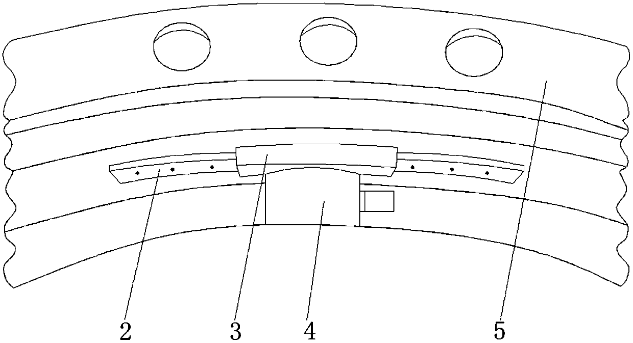
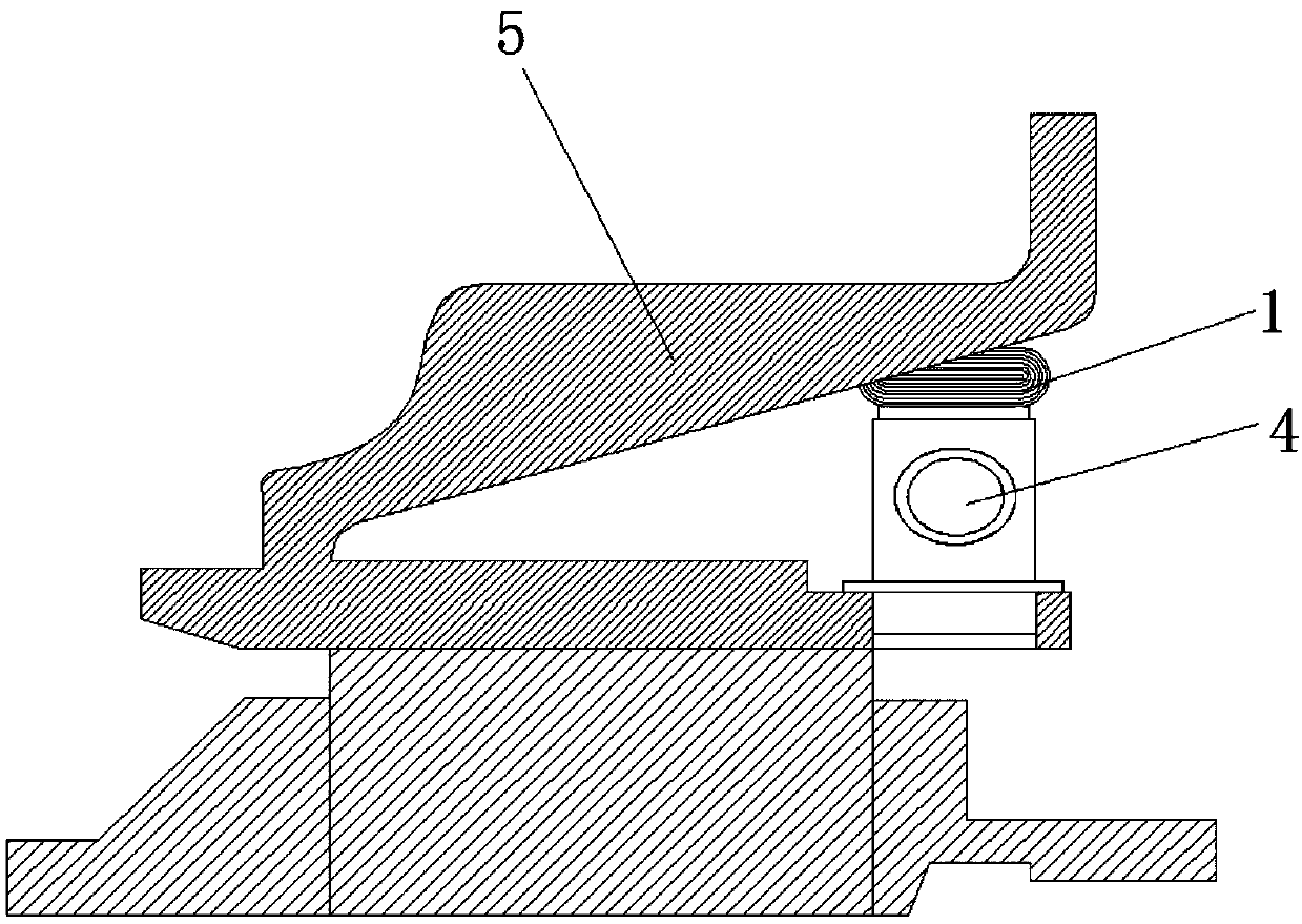
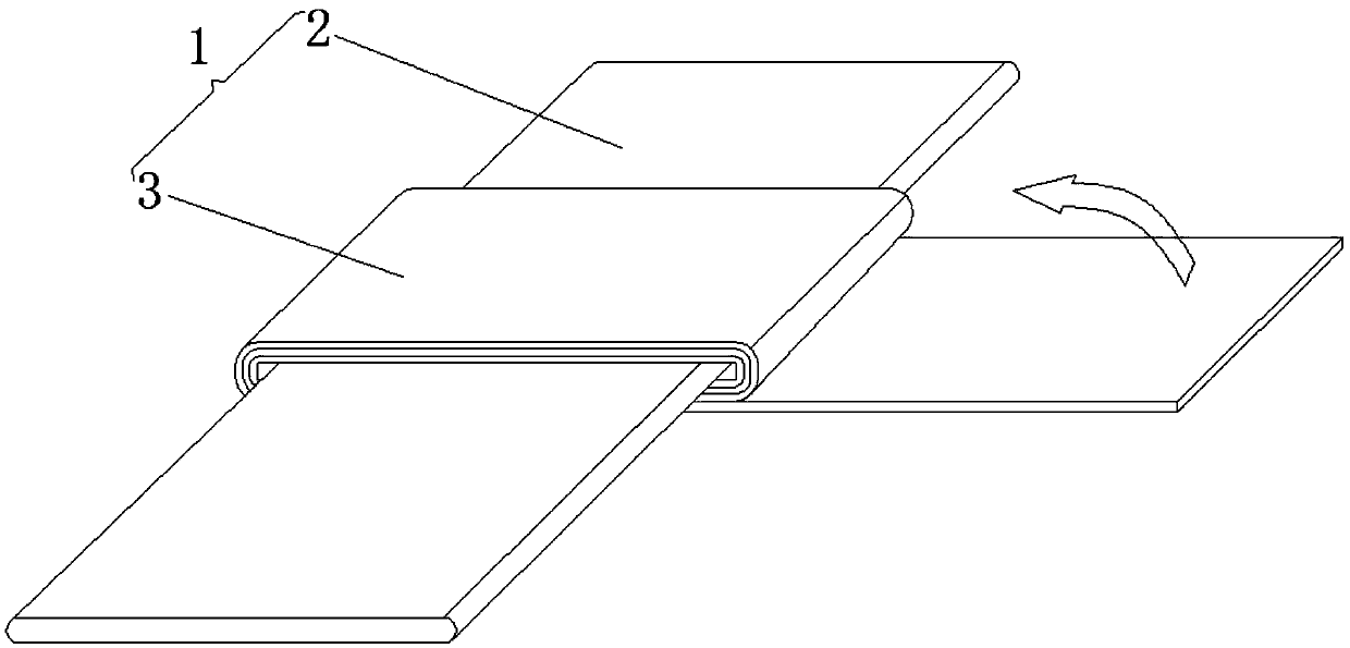
[0018] Such as Figure 1-Figure 3 As shown, an installation and fixing device for a capacitive gap sensor includes a fixing part 1, the fixing part 1 includes a fixing piece 2, and a metal sheet 3 is wound on the outer surface of the fixing piece 2, and the fixing part 1 is located in the capacitive gap In the gap formed between the sensor 4 and the engine component 5, the surface on one side of the metal sheet 3 is closely attached to the end surface of the capacitive gap sensor 4, and the surface on the other side of the metal sheet 3 is closely attached to the surface of the engine component 5. The capacitive clearance sensor 4 is arranged on the engine component 5 .

[0019] The metal sheet 3 is set as a stainless steel sheet.

[0020] A method for installing a capacitive gap sensor, using a device for installing a capacitive gap sensor,...


PUM


Abstract

The present invention provides a mounting and fixing device and a mounting method for a capacitive gap sensor. The device comprises a fixing member, the fixing member comprises a fixing piece, the outer surface of the fixing piece is wound with a metal piece, the fixing piece is located in a gap formed between the capacitive gap sensor and an engine part, the surface of one side of the metal pieceis closely adhered to the end face of the capacitive gap sensor, the surface of the other side of the metal piece is closely adhered to the surface of the engine part, and the capacitive gap sensor is arranged on the engine part. The mounting and fixing device and the mounting method for a capacitive gap sensor employ a mode of winding and filling by employing the metal piece and cooperating withspot welding and fixing to allow the capacitive gap sensor to be closely mounted at the engine measurement portion to ensure that the capacitive gap sensor can be reliably mounted in a narrow and irregular space and ensure the stable work of the sensor in the engine test process.

Description

technical field [0001] The invention belongs to the technical field of aero-engine fluid parameter testing, and in particular relates to an installation and fixing device and an installation method of a capacitive gap sensor. Background technique [0002] Aircraft engine bench clearance measurement is a method used to check the failure of engine rotating parts, mainly using capacitive clearance sensor measurement, but due to the complex and compact structure of the engine, the space for installing the capacitive clearance sensor is very small And irregular, it is generally difficult to ensure the reliable installation of the capacitive gap sensor; usually, the capacitive gap sensor is installed inside the engine. The influence is great. Based on the above two points, the present invention proposes a method for installing and fixing the capacitive gap sensor. Contents of the invention [0003] The invention provides a method for installing and fixing a capacitive gap senso...

Claims


Application Information

Patent Timeline
IPC IPC(8): G01B7/14
CPCG01B7/14
Inventor 吴颖田金光张荫鳌姜凤石丹
Owner SHENYANG LIMING AERO-ENGINE GROUP CORPORATION
Why Eureka
Try Eureka