
Aeroengine fan blade external object impact test platform

A technology for aero-engine and fan blades, which is used in impact testing, mechanical component testing, machine/structural component testing, etc., to achieve the effect of improving engineering

Active Publication Date: 2019-03-29
CHINESE FLIGHT TEST ESTAB
View PDF7 Cites 15 Cited by
  • Summary
  • Abstract
  • Description
  • Claims
  • Application Information

AI Technical Summary

Problems solved by technology

At present, no foreign object impact test platform for fan blades has been developed in China.

Method used


Image

  • Aeroengine fan blade external object impact test platform
  • Aeroengine fan blade external object impact test platform
  • Aeroengine fan blade external object impact test platform

Examples

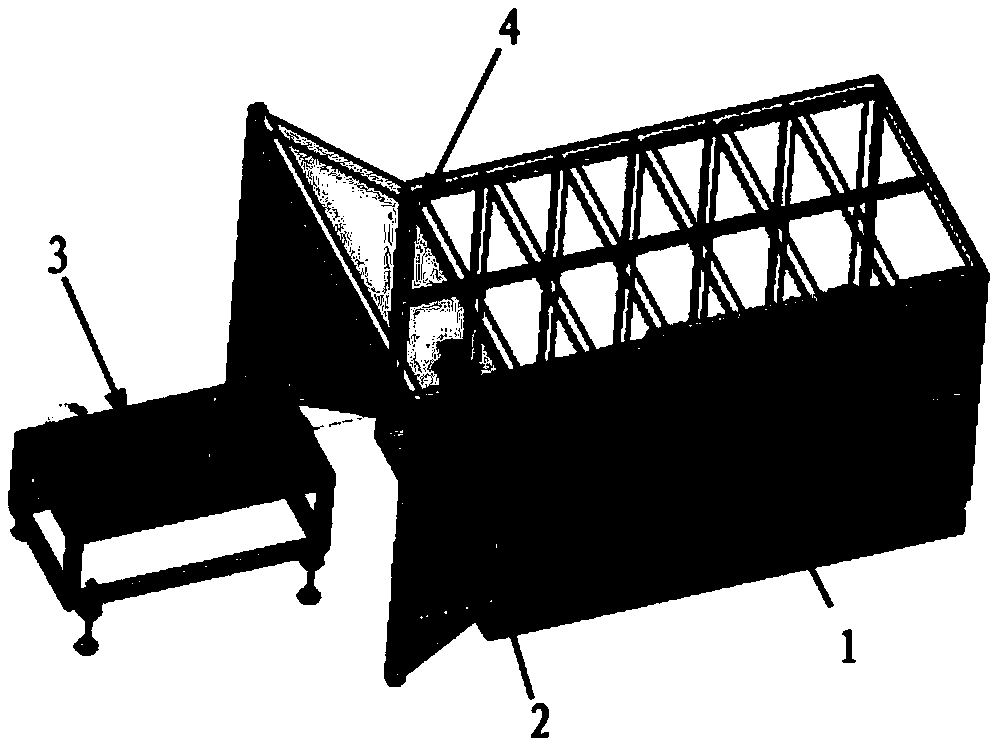
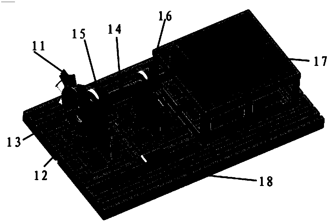
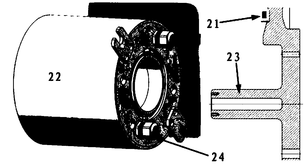

Embodiment Construction

[0025] The following describes the structure of the aero-engine fan blade foreign object impact test platform of the present invention in conjunction with the accompanying drawings, and describes the design idea and implementation method.

[0026] Schematic diagram of the structure of the aero-engine fan blade foreign object impact test platform: figure 1 As shown, it mainly includes the following parts: fan rotor tester 1, fan blade dynamic stress measurement unit 2, test protection unit 3, and foreign object launching device 4. The fan rotor tester 1 and the fan blade dynamic stress measurement unit 2 are located inside the test protection unit 3, and the test protection unit plays a protective role in the impact test of foreign objects; the schematic diagram of the fan blade dynamic stress measurement unit 2 is as follows image 3 As shown, it is assembled on the fan rotor tester 1; the schematic diagram of the foreign object launching device 4 is shown in Figure 4 As sho...


PUM


Abstract

The invention belongs to the technical field of aeroengine fan rotors, and specifically designs an aeroengine fan blade external object impact test platform. The test platform consists of a fan rotortester (1), a fan blade dynamic stress measurement unit (2), a test protection unit (3) and an external object launcher (4). The fan rotor tester (1) adopts a rotor structure of "double fulcrums plusa blade disc cantilever". The test platform can replace a test blade, can launch external objects with various materials, sizes and speeds, can simulate the process of external object impact on an engine fan / compressor blade under various working conditions, can measure and acquire key parameters such as the rotor rotation speed fluctuation, the blade dynamic stress and the rotor vibration the moment the external object impacts, and provides an important test platform for study on the dynamic response of the fan blade, study on blade damage tolerance and study on the real-time monitoring technology of the rotor operation health state.

Description

technical field [0001] The invention belongs to the technical field of aero-engine fan rotors, and specifically designs an aero-engine fan blade foreign object impact test platform. Background technique [0002] When the aircraft takes off, lands or flies at low altitude, sand, stones, birds and other foreign objects may hit the fan blades or other parts at the front of the engine, which will adversely affect the performance and structure of the engine, or even cause serious damage. Inclusive consequences, even catastrophic air crashes. Based on the principle of blade tip timing, by arranging a blade tip vibration sensor on the fan casing, it can be identified whether the fan blade encounters a FOD event. FOD monitoring and identification technology is of great significance for improving flight safety and combat efficiency, improving engine combat readiness integrity and fan blade damage tolerance design. [0003] To apply FOD monitoring and identification technology in fl...

Claims


Application Information

Patent Timeline
Patent Type & Authority Applications(China)
IPC IPC(8): G01M7/08G01M13/00
CPCG01M7/08G01M13/00
Inventor 雷晓波张帅张霞妹彭冲文敏
Owner CHINESE FLIGHT TEST ESTAB
Learn More