
Testing block for magnetic particle inspection depth testing and testing method thereof

A technology of magnetic particle inspection and depth test, applied in the direction of material magnetic variables, etc., can solve the problems of difficult test block processing, inaccurate measurement, poor reliability, etc., and achieve the effect of accurate and reliable test data, simple operation, and avoidance of interference.

Pending Publication Date: 2019-04-02
DONGFANG BOILER GROUP OF DONGFANG ELECTRIC CORP
View PDF12 Cites 8 Cited by
  • Summary
  • Abstract
  • Description
  • Claims
  • Application Information

AI Technical Summary

Problems solved by technology

Using the test method of pre-embedded specific depth defect test block, it is difficult to control the depth control of the embedded defect, the processing of the test block is difficult, the buried depth of the defect is discrete, and the measurement is not accurate enough; the test method of the back cut groove test block is adopted, because the magnetic circuit is opened by the back The large-area groove is blocked, and the magnetic force lines are highly compressed near the surface of the workpiece to form magnetic saturation, so that the magnetic force lines overflow the surface of the workpiece in a large amount, which is very different from the magnetic field distribution generated by the buried defects in the actual inspected workpiece. poor reliability

Method used


Image

  • Testing block for magnetic particle inspection depth testing and testing method thereof
  • Testing block for magnetic particle inspection depth testing and testing method thereof
  • Testing block for magnetic particle inspection depth testing and testing method thereof

Examples


Embodiment 1

[0042] In this embodiment, the application of the present invention is described by taking the supplementary detection of the near-surface blind area in the TOFD detection of the butt weld of our company as an example. TOFD detection is ultrasonic diffraction time-of-flight method, which is a method to detect defects by relying on the diffraction energy obtained from the "end angle" and "end point" of the internal structure of the test piece (mainly refers to the defect), and is used for defect detection , quantification and positioning, but this method has a detection blind area near the surface, and the detection reliability of the near surface area is not enough. Therefore, after TOFD testing, magnetic particle testing can be used for supplementary testing of the near-surface area.

[0043] According to the requirements of NB / T47013.10-2015 "Ultrasonic Testing of Diffraction Time-of-flight for Non-destructive Testing of Pressure Equipment", it is necessary to implement supp...


PUM


Abstract

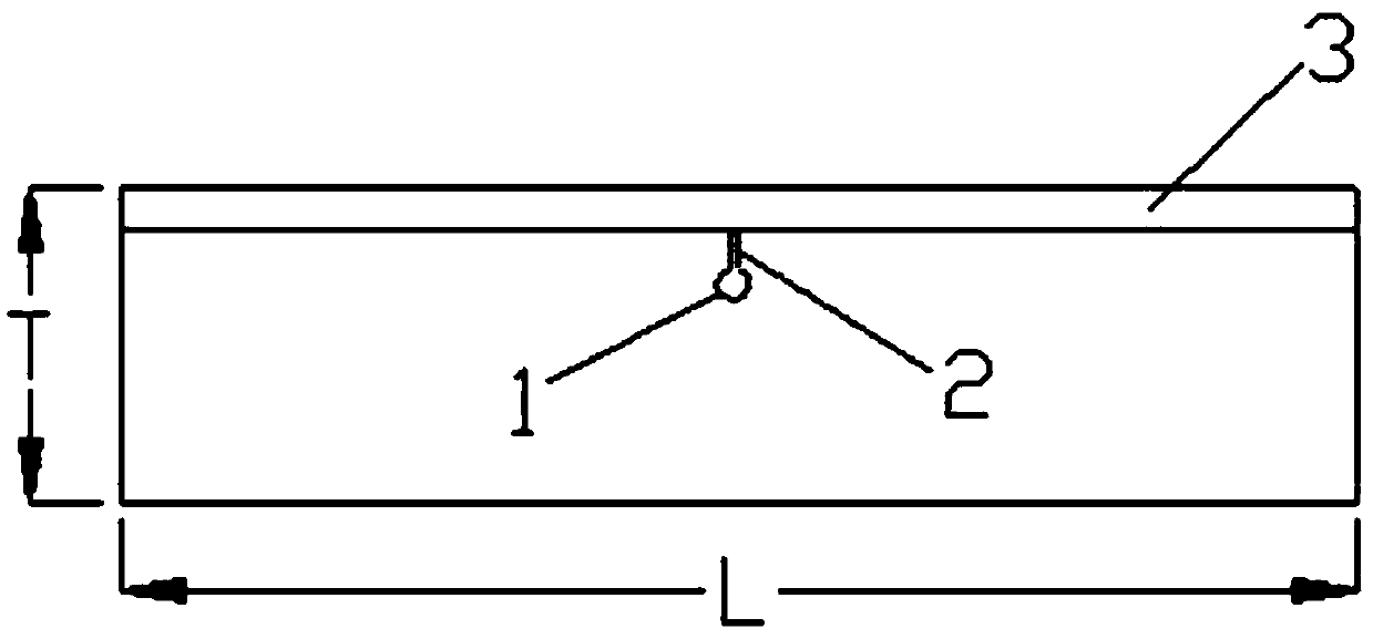
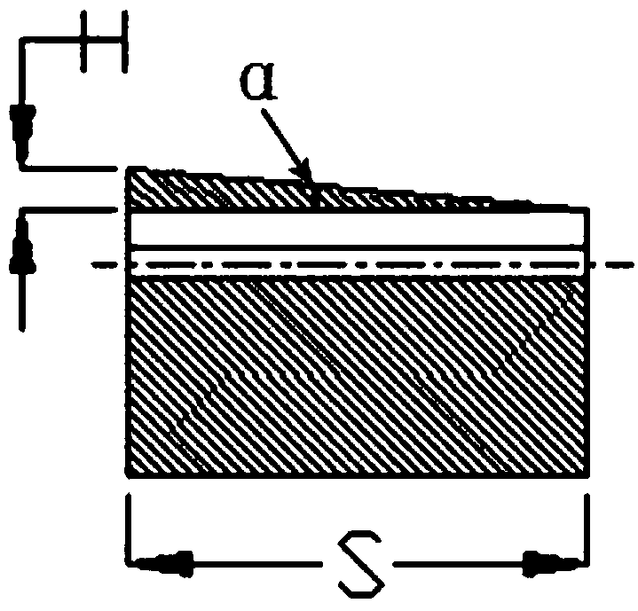
The invention relates to a testing block for a magnetic particle inspection depth testing and a testing method thereof. One surface of the testing block is used as an inspecting surface for the magnetic particle inspection depth testing. A strip-shaped groove body for simulating the buried defects of the welding is formed under the inspecting surface. The inspecting surface is obliquely arranged relative to the strip-shaped groove body. One side of the inspecting surface is connected with the top edge of one end of the strip-shaped groove body. An angle alpha is formed between the inspecting surface and the strip-shaped groove body. The alpha is 1.5 to 5 degrees. According to the testing block, the depth between the strip-shaped groove body and the inspecting surface is continuously changed, so that the buried defects which continuously changes in depth can be simulated. In the magnetic particle inspection depth testing, the magnetic particle inspection depth can be calculated by measuring the track display length generated by the strip-shaped groove body. Therefore, the testing block can be used for a magnetic particle inspection lifting force testing, the equipment selection andthe process parameter selection of a magnetic particle inspection, the process verification of a magnetic particle supplementation inspection of TOFD surface dead zones and the like.

Description

technical field [0001] The invention relates to the field of non-destructive testing, in particular to the field of magnetic powder testing. Background technique [0002] In the quality inspection of boilers, containers, pipelines, nuclear power, military and other products, magnetic particle inspection is one of the most widely used nondestructive inspection methods. The principle is to form magnetic force lines in the workpiece by passing magnetism or electricity to the workpiece. When there are surface or near-surface defects in the area, the magnetic force lines will choose the path of minimum reluctance to pass because they are blocked by the defects, so that the original magnetic force lines will be distorted, and may overflow the workpiece surface at the defect to form a leakage magnetic field. After ferromagnetic powder or magnetic suspension containing ferromagnetic powder, the leakage magnetic field overflowing the surface of the workpiece will attract and gather f...

Claims


Application Information

Patent Timeline
IPC IPC(8): G01N27/84
CPCG01N27/84
Inventor 谭云华赖传理吴志波石爱玲谢进吴乾刚刘勇
Owner DONGFANG BOILER GROUP OF DONGFANG ELECTRIC CORP
Learn More