
Railway crane

A crane and railway technology, applied in the direction of cranes, etc., can solve the problems of high-speed return, small load, heavy return shaft, etc., to meet the rescue requirements, reduce the return shaft weight, and increase the contact area.

Inactive Publication Date: 2019-04-05
CHINA RAILWAYS CORPORATION +1
View PDF10 Cites 2 Cited by
  • Summary
  • Abstract
  • Description
  • Claims
  • Application Information

AI Technical Summary

Problems solved by technology

[0003] Among them, the telescopic boom has a three-section structure, and a set of sliding blocks for wear-resistant and load-bearing are respectively provided on the front inner wall of the first section boom (located at the rearmost end of the vehicle body) and the front end inner wall of the second section boom, but due to the The section of the arm is polygonal, such as a hexagonal or octagonal structure, so each set of sliders can only be set along the sides of the polygon, and the sliders cannot be set at the position where the two sides meet, that is, the sliders The number of settings is limited, and the total force-bearing area is limited, so that the load-bearing position of each slider in contact with the boom is relatively large. In order to ensure the strength, the thickness requirements for the second and third booms are also higher. Large, which leads to heavy weight of railway cranes
[0004] Since trains operating on high-speed railways are mainly designed for carrying passengers rather than cargo, compared with the standard design of ordinary railway lines, bridges can bear less load, and the time for fault rescue on high-speed railways is more critical. The railway crane with a large dead weight makes the return axle load (the weight carried by each axle) larger, and cannot be returned at high speed on the high-speed railway, resulting in a long rescue time and unable to meet the rescue requirements.

Method used


Image

  • Railway crane
  • Railway crane
  • Railway crane

Examples


Embodiment Construction

[0052] In order to enable those skilled in the art to better understand the technical solution of the present invention, the present invention will be further described in detail below in conjunction with the accompanying drawings and specific embodiments.

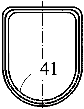
[0053] Please refer to Figure 1-9 , figure 1 It is a structural schematic diagram of a railway crane according to an embodiment of the present invention; figure 2 yes figure 1 Sectional view of the boom with load-bearing area in ; image 3 yes figure 1 Schematic diagram of the installation structure of the support mechanism and the chassis in ; Figure 4 yes image 3 top view of Figure 5 yes figure 1 Schematic diagram of the structure of the middle main leg; Figure 6 yes Figure 5 top view of Figure 7 yes figure 1 Schematic diagram of the structure of the medium and heavy iron telescopic arm; Figure 8 It is a structural schematic diagram of a railway crane equipped with an auxiliary support frame in an em...


PUM


Abstract

The invention relates to a railway crane. The railway crane comprises two bogies, a bottom frame, a rotating table, a stretchable lifting arm and a supporting mechanism, wherein the bottom frame is arranged at the upper ends of the two bogies, the rotating table is rotatably arranged at the upper end of the bottom frame, one end of the stretchable lifting arm is connected with the rotating table,the supporting mechanism is connected with the bottom frame, the lifting arm comprises at least two expansion joints, in every two adjacent expansion joints, a bearing area is formed at the lower partof the inner wall of the end, facing the inner expansion joint, of the outer expansion joint, a cross section of each bearing area is arc-shaped, and a plurality of sliding blocks are arranged in parallel along the circumferential direction of each bearing area. According to the railway crane, the dead weight can be effectively reduced, so that the railway crane can be suitable for carrying out rescue operation on a high-speed railway bridge and line, the rescue time can be effectively shortened, and the rescue requirements can be met.

Description

technical field [0001] The invention relates to the technical field of railway rescue, in particular to a railway crane. Background technique [0002] The existing railway cranes are designed according to the standard of ordinary railway lines, and are used for rescue and large-scale cargo lifting operations on ordinary railway lines. frame and support mechanism with four legs. [0003] Among them, the telescopic boom has a three-section structure, and a set of sliding blocks for wear-resistant and load-bearing are respectively provided on the front inner wall of the first section boom (located at the rearmost end of the vehicle body) and the front end inner wall of the second section boom, but due to the The section of the arm is polygonal, such as a hexagonal or octagonal structure, so each set of sliders can only be set along the sides of the polygon, and the sliders cannot be set at the position where the two sides meet, that is, the sliders The number of settings is l...

Claims


Application Information

Patent Timeline
Patent Type & Authority Applications(China)
IPC IPC(8): B66C23/84B66C23/69B66C23/78B66C23/50
CPCB66C23/50B66C23/701B66C23/78B66C23/84
Inventor 刘永于跃于跃斌于维王会武白圣男潘聚才任冬青王培武徐国辉钮承陈国
Owner CHINA RAILWAYS CORPORATION
Learn More