Protective rack mechanism used for small-load machinery

A small load, tooth protection technology, applied in the direction of mechanical equipment, belts/chains/gears, transmission parts, etc., can solve the problems that the gears cannot be continuously moved, the end teeth are broken, and the head end of the rack cannot be maintained, etc.

Inactive Publication Date: 2019-04-05
深圳市安达工业设计有限公司
View PDF0 Cites 4 Cited by
  • Summary
  • Abstract
  • Description
  • Claims
  • Application Information

AI Technical Summary

Problems solved by technology

However, when the gear continues to move the end of the rack, the teeth at the end of the rack will continue to be moved by the gear, and the teeth at the end of the rack will be more likely to cause wear and tear, and even cause the end teeth to be worn off.

Method used


Image

  • Protective rack mechanism used for small-load machinery
  • Protective rack mechanism used for small-load machinery
  • Protective rack mechanism used for small-load machinery

Examples


specific Embodiment approach

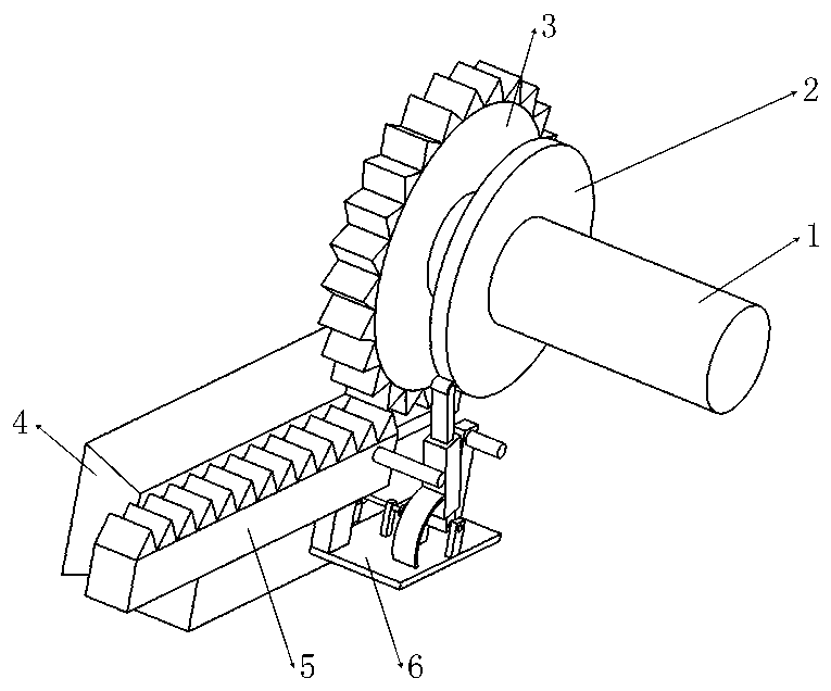
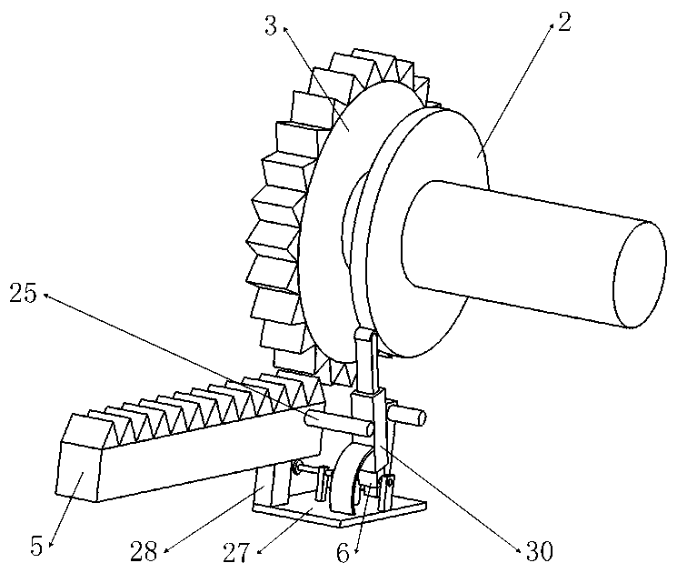
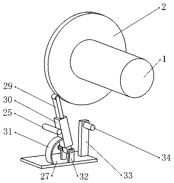
[0054] Specific embodiments: when the power unit in the small-load mechanical mechanism does not drive the drive shaft 1 to rotate, the friction wheel 2 and the drive gear 3 do not rotate. The first spring 12 is in the natural state, the limit plate 48 on the drive rack 5 is not limited by the limit block 13, the third gear 46 does not mesh with the first rack 16, and the leaf spring 31 is in the natural state. The drive gear 3 is in mesh with the drive rack 5 .

[0055]When the power unit in the small-load mechanical mechanism drives the drive shaft 1 to rotate forward, the drive shaft 1 drives the drive gear 3 and the friction wheel 2 to rotate forward, as Figure 4 , 19 As shown, the rotation direction of the friction wheel 2 and the drive gear 3 is set to be clockwise at this time. The forward-rotating driving gear 3 drives the driving rack 5 to move, the first trapezoidal slider 10 moves following the driving rack 5, and the first spring 12 is stretched; the limiting pl...


PUM


Abstract

The invention belongs to the technical fields of rack, and particularly relates to a protective rack mechanism used for small-load machinery. The protective rack mechanism comprises a friction wheel,a drive gear, a first trapezoidal slide rail, a drive rack, a protective mechanism, a first trapezoidal slide block, a first spring and a limiting block, wherein after the drive gear drives the driverack to move to a limit position, i.e., when a limiting plate on the drive rack is on a position limited by the limiting block, the drive gear cannot continuously pull a tooth at the tail end of the drive rack while the design that the limiting plate is limited by the limiting block enables the drive rack to keep on a position to be reached after being driven by the drive rack, and further can enable the drive rack to pull to a precise position by the drive gear. The limiting plate is matched with the limiting block for limiting, so that the drive gear is prevented from continuously pulling the tooth at the tail end of the drive rack, and mechanical abrasion, caused when the tooth at the tail end of the drive rack is continuously pulled, is avoided, and therefore, a condition that the drive rack cannot be precisely pulled to an accurate position by the drive gear is avoided.

Description

technical field [0001] The invention belongs to the technical field of racks, and in particular relates to a protection rack mechanism for small-load machines. Background technique [0002] At present, in the mechanical structure of small load, the structure in which the gear and the rack are meshed is often used. In the structure in which the gear and the rack are meshed, there is a driving structure in which the gear drives the rack to move. In the type of gear-driven rack, there is a gear that drives the rack to a specific position through continuous rotation, and the gear will continue to move the end of the rack to ensure that the first section of the rack can maintain a specific position. However, when the gear continues to move the end of the rack, the teeth at the end of the rack will continue to be moved by the gear, and the teeth at the end of the rack will be more likely to cause wear and tear, and even cause the end teeth to be worn off. At this time, the teeth...

Claims


Application Information

Patent Timeline
IPC IPC(8): F16H19/04F16H57/00
CPCF16H19/04F16H57/00
Inventor 陈红
Owner 深圳市安达工业设计有限公司
Why Eureka
Try Eureka