Electronic level collimation vertical line offset determination calibration method

An electronic level and calibration method technology, applied in the direction of instruments, measuring devices, etc., can solve the problems of normal measurement, troublesome maintenance, and the inability of the electronic level to accurately target the coding scale, so as to improve the on-site adjustment ability and work efficiency. Accurate and ensure the effect of correct use

Active Publication Date: 2019-04-05
DALIAN SENBIOR SURVEYING INSTR TECH CO LTD
View PDF6 Cites 0 Cited by
  • Summary
  • Abstract
  • Description
  • Claims
  • Application Information

AI Technical Summary

Problems solved by technology

When the observation distance is relatively short, it has little effect on the aiming of the electronic level. When the observation distance is long, if the surveyor still conducts aiming according to the vertical marking of the reticle, the electronic level cannot be accurately aimed. Encoding the ruler and not measuring normally
Since the vertical marking on the reticle plate of the level is fixed, if it is returned to the factory for maintenance, only the position of the electronic readout (CCD) can be adjusted, which not only troubles maintenance but also affects the working efficiency of the measuring unit

Method used


Image

  • Electronic level collimation vertical line offset determination calibration method
  • Electronic level collimation vertical line offset determination calibration method
  • Electronic level collimation vertical line offset determination calibration method

Examples


Embodiment

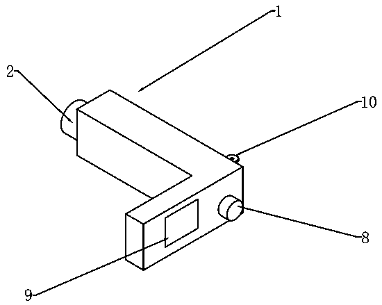
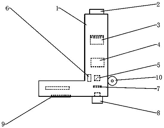
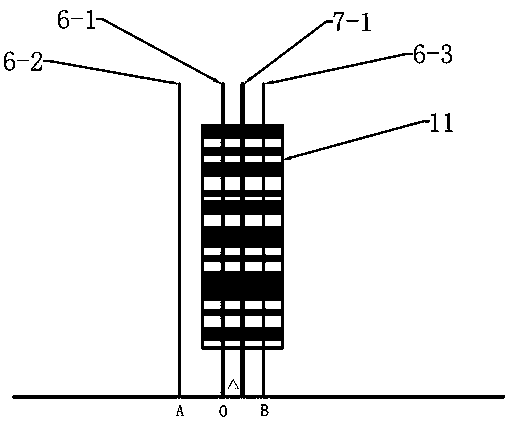
[0015] The method for measuring and calibrating the offset of the electronic level aiming at the vertical line of the present invention has an electronic level, and the structure of the electronic level is as follows: figure 1 , 2 As shown: there is a housing 1, in which there are objective lens 2, focusing lens 3, automatic horizontal line of sight compensator 4, beam splitter 5, electronic reading device 6 (that is, the CCD image decoding used in conjunction with the coding level scale reading device), reticle 7, electronic eyepiece 8, and a display terminal 9 and a level 10 are also provided on the housing 1. The display terminal 9 is composed of a display screen and buttons. The same coding scale 11; follow the steps below in turn:

[0016] a. Use the auxiliary tripod to place the electronic level and the coded scale 11 on two points on the ground respectively according to the method of the prior art, level the electronic level so that the coded scale 11 is vertical and f...


PUM


Abstract

The invention discloses an electronic level collimation vertical line offset determination calibration method. The electronic level collimation vertical line offset determination calibration method comprises the following steps that the offset between a vertical induction reading center line of a figure reading electronic device and a reticule plate vertical marking line is determined by determining left and right limit positions for ensuring the normal reading of an electronic level; the vertical induction reading center line of the figure reading electronic device is calibrated by using a mechanical or electronic method; and the center position of a coding scale is collimated by using the calibrated vertical induction reading center line of the figure reading electronic device. The accurate collimation of the electronic level is achieved, the correct use of the electronic level is ensured, and the on-site adjustment capability and working efficiency of surveyors are improved.

Description

technical field [0001] The invention relates to a leveling instrument calibration method in the fields of geodetic surveying and engineering surveying, in particular to a method for measuring and calibrating the deviation of an electronic leveling instrument's aiming vertical line. Background technique [0002] Existing level measuring device is made up of a level instrument and two level rulers. The electronic level consists of an objective lens, a focusing lens, an automatic horizontal line of sight compensator, a beam splitter, a crosshair reticle, an electronic eyepiece, an electronic readout and a display and control terminal. When measuring, first place the two leveling rods vertically at the two points A and B on the ground, and then set the level at the middle position of the two points A and B, and use the leveling telescope to collimate the axis (that is, the intersection point of the crosshair and the The line of sight provided by the optical center of the object...

Claims


Application Information

Patent Timeline
Patent Type & Authority Applications(China)
IPC IPC(8): G01C25/00
CPCG01C25/00
Inventor 刘雁春
Owner DALIAN SENBIOR SURVEYING INSTR TECH CO LTD
Why Eureka
Try Eureka