
Transformer fault detection device based on infrared imaging technology

A technology of transformer fault and detection device, applied in the direction of measuring device, instrument, measuring electricity, etc., can solve problems such as waste of manpower and material resources, large transformer volume, delay in fault diagnosis time, etc., to achieve good flexibility, good adaptability, and avoid faults The effect of diagnosis time

Pending Publication Date: 2019-04-05
NINGBO ELECTRIC POWER DESIGN INST
View PDF0 Cites 2 Cited by
  • Summary
  • Abstract
  • Description
  • Claims
  • Application Information

AI Technical Summary

Problems solved by technology

However, due to the large size of the transformer itself, it is difficult to accurately locate the fault location by infrared detection, and further manual inspection is required to carefully check, which will inevitably lead to omissions or misjudgments, and waste a lot of manpower and material resources, delaying the fault diagnosis time
Therefore, it is necessary to design a transformer fault detection device based on infrared imaging technology, which can detect the transformer around the transformer, realize the circular detection of the whole body of the transformer, ensure the detection accuracy, and avoid delaying the fault diagnosis time

Method used


Image

  • Transformer fault detection device based on infrared imaging technology
  • Transformer fault detection device based on infrared imaging technology
  • Transformer fault detection device based on infrared imaging technology

Examples


Embodiment Construction

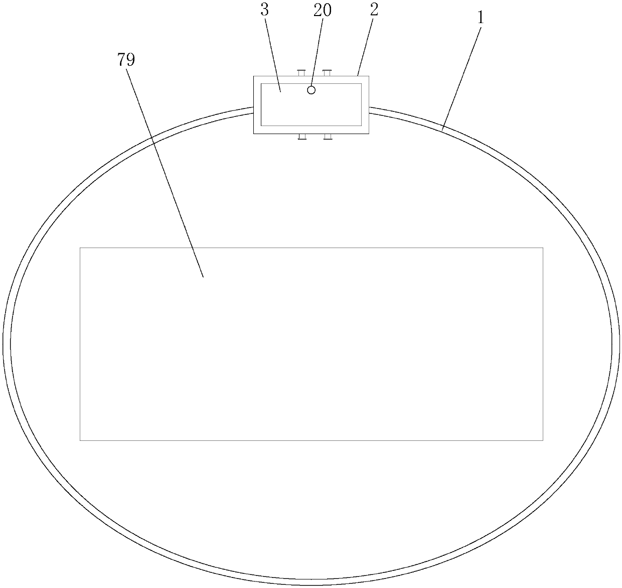
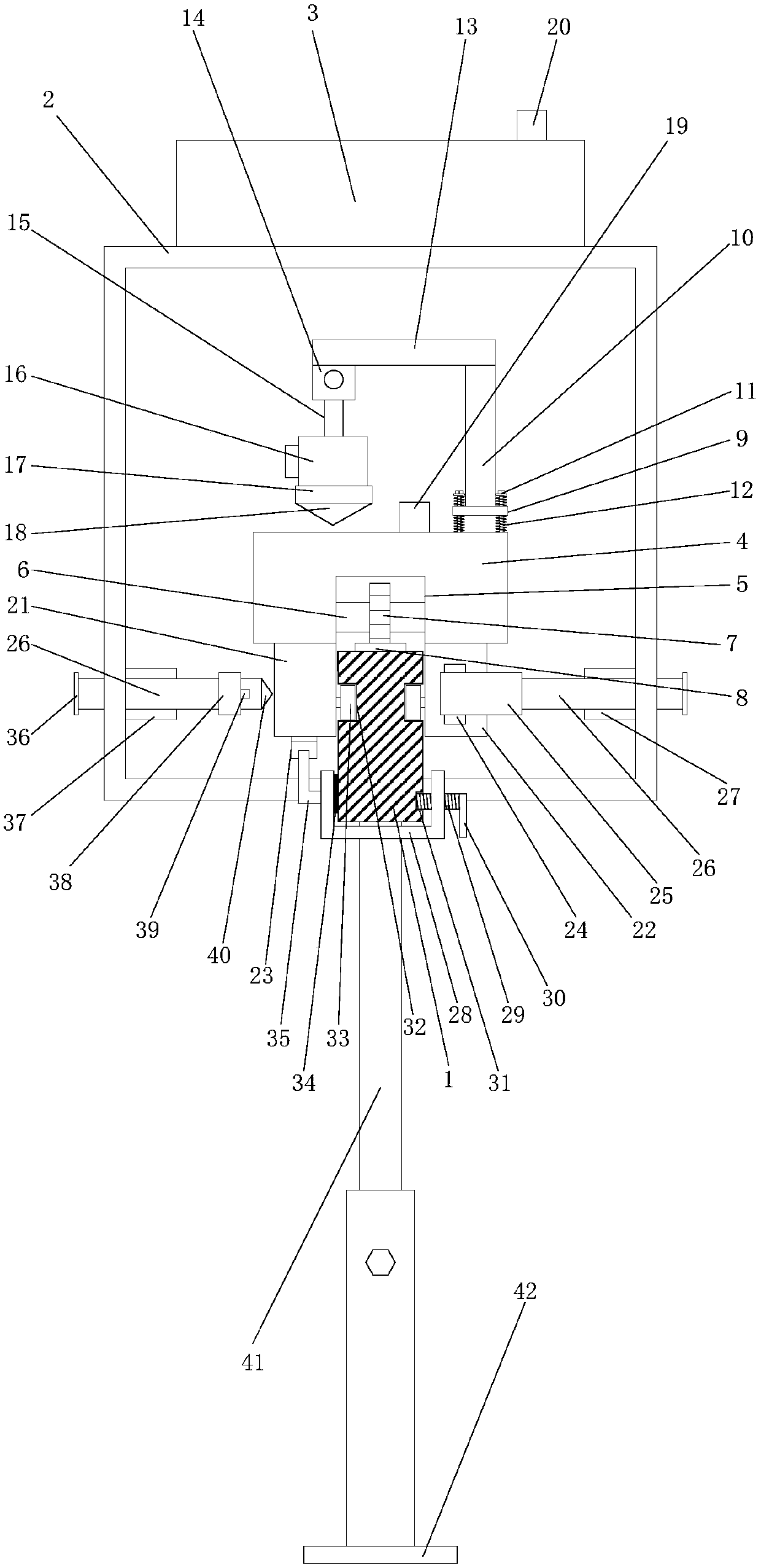
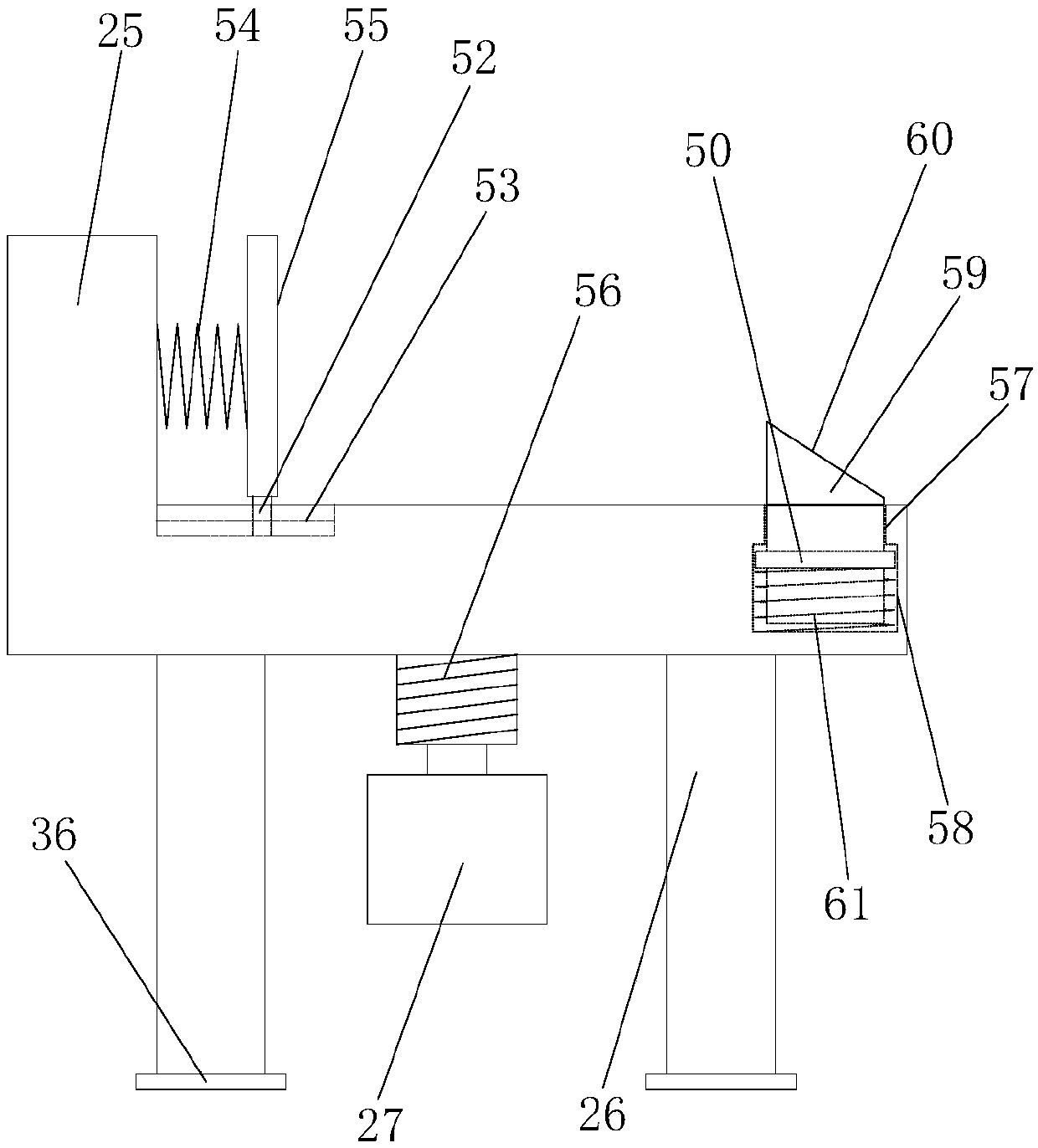
[0022] Such as Figure 1-7 As shown, the transformer fault detection device based on infrared imaging technology disclosed by the present invention includes: a remote server, a cruise track 1, a protective cover 2, a terminal control box 3, a mobile shooting mechanism and each shooting trigger mechanism; the cruise track 1 is a circular track , is arranged around the periphery of the transformer 79 through each track support structure; the track support structure is composed of a vertical support rod 41, a vertical insertion tube, a lower end plate 42 and a height adjustment bolt; the upper end of the vertical support rod 41 is fixedly installed on the cruise On the lower side of the track 1, the lower end is inserted into the vertical insertion tube; the lower end plate 42 is fixedly installed on the lower end of the vertical insertion tube; the height adjustment bolt is threaded and installed on the tube wall of the vertical insertion tube and the screw end of the height adj...


PUM


Abstract

The invention provides a transformer fault detection device based on an infrared imaging technology. The transformer fault detection device comprises a remote server, a cruise track, a protective cover, a terminal control box, a mobile shooting mechanism and shooting trigger mechanisms. The cruise track is arranged around the periphery of a transformer, and the mobile shooting mechanism is installed on the cruise track. The protective cover is installed on the cruise track, the terminal control box is installed on the protective cover, and the shooting trigger mechanisms are installed at eachmonitoring point on the cruise track. According to the transformer fault detection device, the cruise track is arranged around the periphery of the transformer by using each track supporting structure, so that the mobile shooting mechanism can shoot around the transformer, the transformer can be rapidly and comprehensively detected, and the fault diagnosis time is prevented from being delayed; andthe shooting trigger mechanisms are installed on the cruise track, so that infrared photography can be conveniently carried out at each key detection position according to monitoring requirements, and the transformer fault detection device has better adaptability on field installation.

Description

technical field [0001] The invention relates to a transformer fault detection device, in particular to a transformer fault detection device based on infrared imaging technology. Background technique [0002] With the continuous expansion of the scale of my country's power grid and the rapid development of smart grids, it is particularly important to be able to quickly and accurately judge whether electrical equipment fails. advantages, it has been widely used. However, due to the large size of the transformer itself, it is difficult to accurately locate the fault location by infrared detection, and further manual inspection is required to carefully check, which will inevitably lead to omissions or misjudgments, and waste a lot of manpower and material resources, delaying the fault diagnosis time. Therefore, it is necessary to design a transformer fault detection device based on infrared imaging technology, which can perform surrounding detection on the transformer, realize t...

Claims


Application Information

Patent Timeline
Patent Type & Authority Applications(China)
IPC IPC(8): G01R31/00G01J5/00
CPCG01J5/00G01R31/00G01J2005/0077
Inventor 马益平余萃卓钱凯郭高鹏李敏敏邵雪峰王正勇王丽鹏
Owner NINGBO ELECTRIC POWER DESIGN INST
Learn More