Combined adjustment device for adjusting post insulators and adjustment method

A pillar insulator and joint adjustment technology, applied in switchgear, electrical components and other directions, can solve the problem of not being able to adjust the vertical and horizontal deviation of multiple pillar insulators at the same time. Effect

Active Publication Date: 2019-04-05
QINGHAI POWER TRANSMISSION & TRANSFORMATION ENG +2
View PDF6 Cites 1 Cited by
  • Summary
  • Abstract
  • Description
  • Claims
  • Application Information

AI Technical Summary

Problems solved by technology

[0006] Aiming at the deficiencies of the existing technology, the present invention provides a joint adjustment device and adjustment method for adjusting post insulators, which solves the technical problem in the prior art that the vertical and horizontal deviations between multiple post insulators cannot be adjusted at the same time

Method used


Image

  • Combined adjustment device for adjusting post insulators and adjustment method
  • Combined adjustment device for adjusting post insulators and adjustment method
  • Combined adjustment device for adjusting post insulators and adjustment method

Examples


Embodiment 1

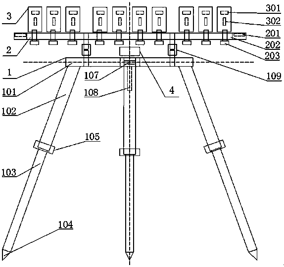
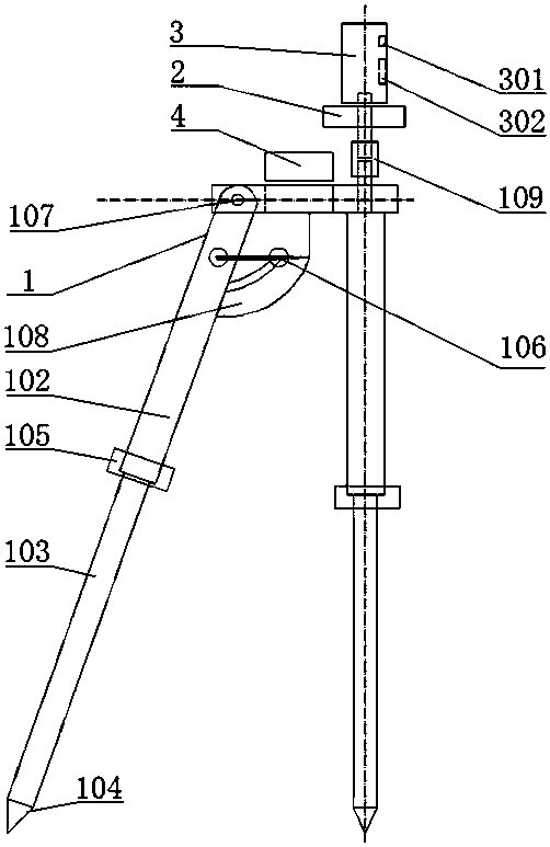
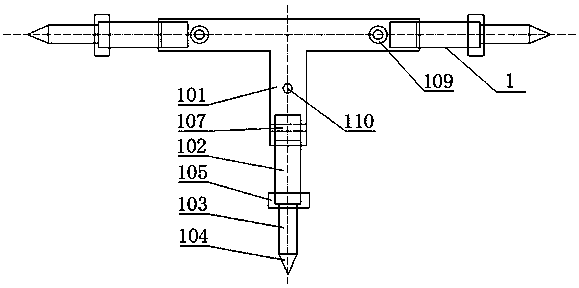
[0051] Example 1, such as Figure 1-Figure 7 , a joint debugging device for adjusting post insulators, characterized in that it includes a tripod (1), a horizontal base (2), a laser transmitter (3), a power box (4), a series compensation platform (5), Post insulators (6);

[0052] The upper part of the triangular support (1) is a T-shaped support base (101), and the lower part has three supporting legs, and each supporting leg is composed of an upper joint supporting leg (102), a lower joint supporting leg (103), and a foot nail (104) Composition, in which two upper legs (102) and the two ends of the cross arm of the T-shaped bracket base (101) are fixedly connected, and one upper segment leg (102) and the T-shaped bracket base (101) pass through the rotating shaft (107 ) is connected with the angle measuring instrument (108), and the angle measuring instrument (108) is provided with a locking bolt A (106); the lower end of the upper leg (102) is connected with the lower leg ...

Embodiment 2

[0065] Example 2, such as Figure 7 , the present invention provides an adjustment method for adjusting a joint adjustment device of a post insulator, comprising the following steps:

[0066] Step 1, mark the ball socket (601) and the center lines on both sides of ball head A (501) and ball head B (603), and mark the center lines on both sides of the upper and lower ends of the post insulator (6);

[0067] Step 2, set two triangular brackets (1) on the ground directly in front of and on the side of a group of post insulators (6), and the two outriggers fixedly connected to the T-shaped bracket base (101) are supported near the post insulators ( 6) On one side, the other leg is supported on the side away from the post insulator (6). Use the lower leg (103) to preliminarily level the triangular bracket (1) and tighten the nut (105). Check the angle measuring instrument (108) indicates zero degrees and lock the locking bolt A (106);

[0068] Step 3, connect the tripod bracket (...


PUM


Abstract

The invention provides a combined adjustment device for adjusting post insulators and an adjustment method and relates to the technical field of substation electrical equipment installation. The structure of the device comprises a triangular bracket, a horizontal base, laser transmitters, a power supply box, a series compensation platform and the post insulators. Laser rays emitted by a laser transmitter form vertical and horizontal laser faces, and multiple laser transmitters form a plurality of vertical laser faces and a horizontal laser face for adjusting the verticality and horizontal heights of the post insulators. The invention has the advantages that the combined adjustment device can quickly adjust the vertical and horizontal degrees of the post insulators by observing the projection of the laser transmitters, series compensation platform bottom ball heads and post insulator ball sockets are precisely connected by the device and the adjustment method, the connection adjustmenttime of the platform in air is greatly shortened, the installation precision is improved, the operation process is simple, the detection efficiency, the precision are high, and the device and the method can be used by simultaneously adjusting the vertical and horizontal degrees of the multiple post insulators.

Description

technical field [0001] The invention belongs to the technical field of substation electrical equipment installation, and relates to the installation of post insulators on a series compensation platform of a series compensation device, in particular to a joint adjustment device and an adjustment method for adjusting post insulators. Background technique [0002] The steel structure platform of the series compensation device is referred to as the series compensation platform, which is the carrier for the installation and operation of the electrical equipment of the series compensation device. The installation quality of the series compensation platform plays an important role in the safe and reliable operation of the series compensation device. [0003] The series compensation platform is a planar frame structure connected by three longitudinal main girders and multiple horizontal auxiliary girders, with large dimensions and heavy weight; it is installed in the air at a certain...

Claims


Application Information

Patent Timeline
Patent Type & Authority Applications(China)
IPC IPC(8): H02B3/00
CPCH02B3/00
Inventor 张灵利吴建平吴兴波程志国杨涛郑国彪闫西利羊刚曹仕奇刘帅张海钊甘生霖王永明
Owner QINGHAI POWER TRANSMISSION & TRANSFORMATION ENG
Why Eureka
Try Eureka