Dimmable switching mode LED driving circuit without phase angle measurement

a driving circuit and dimming circuit technology, applied in the direction of electroluminescent light sources, electric lighting sources, semiconductor lamp usage, etc., can solve the problems of inability to achieve dimming function, damage to the components of the driving circuit, and ineffective operation of the dimmer circuit, etc., to achieve simple and robust control mechanisms, high power factor, and fast adjustment of level

Inactive Publication Date: 2016-11-15
ALITEK TECH
View PDF4 Cites 1 Cited by
  • Summary
  • Abstract
  • Description
  • Claims
  • Application Information

AI Technical Summary

Benefits of technology

[0013]Another objective of the present invention is to disclose a dimmable switching mode LED driving circuit, which uses a simple and robust control mechanism to quickly adjust the level of an output current in response to a phase-cut AC voltage to provide a dimming function.
[0014]Still another objective of the present invention is to disclose a dimmable switching mode LED driving circuit, which provides a high power factor and a constant output current even when no phase cutting dimmer is connected thereto.

Problems solved by technology

However, when a dimmer circuit for providing a dimming function is placed between a standard AC voltage and the generally designed switching mode LED driving circuit, the operation of the dimmer circuit can be ineffective in dimming the LED lamp.
Besides, as the phase-cut AC voltage has a less conduction time than a standard AC voltage, to make a same constant output current, the peaks of the input switching current caused by the phase-cut AC voltage will be higher than the peaks of the input switching current caused by the standard AC voltage, and the higher peaks of the input switching current can cause damage to the components of the driving circuit.
However, with the level of the constant output current remains unchanged, the dimming function will not be achievable.
However, as a TRIAC voltage (VTRC) of the triac-based dimmer 20 tends to be noisy, the phase angle detection circuit of the dimmable switching mode LED driving circuit of FIG. 2 has to be carefully designed.
Besides, using the phase angle as a variable in determining the reference current level will make the entire control circuit much more complex.

Method used


Image

  • Dimmable switching mode LED driving circuit without phase angle measurement
  • Dimmable switching mode LED driving circuit without phase angle measurement
  • Dimmable switching mode LED driving circuit without phase angle measurement

Examples


Embodiment Construction

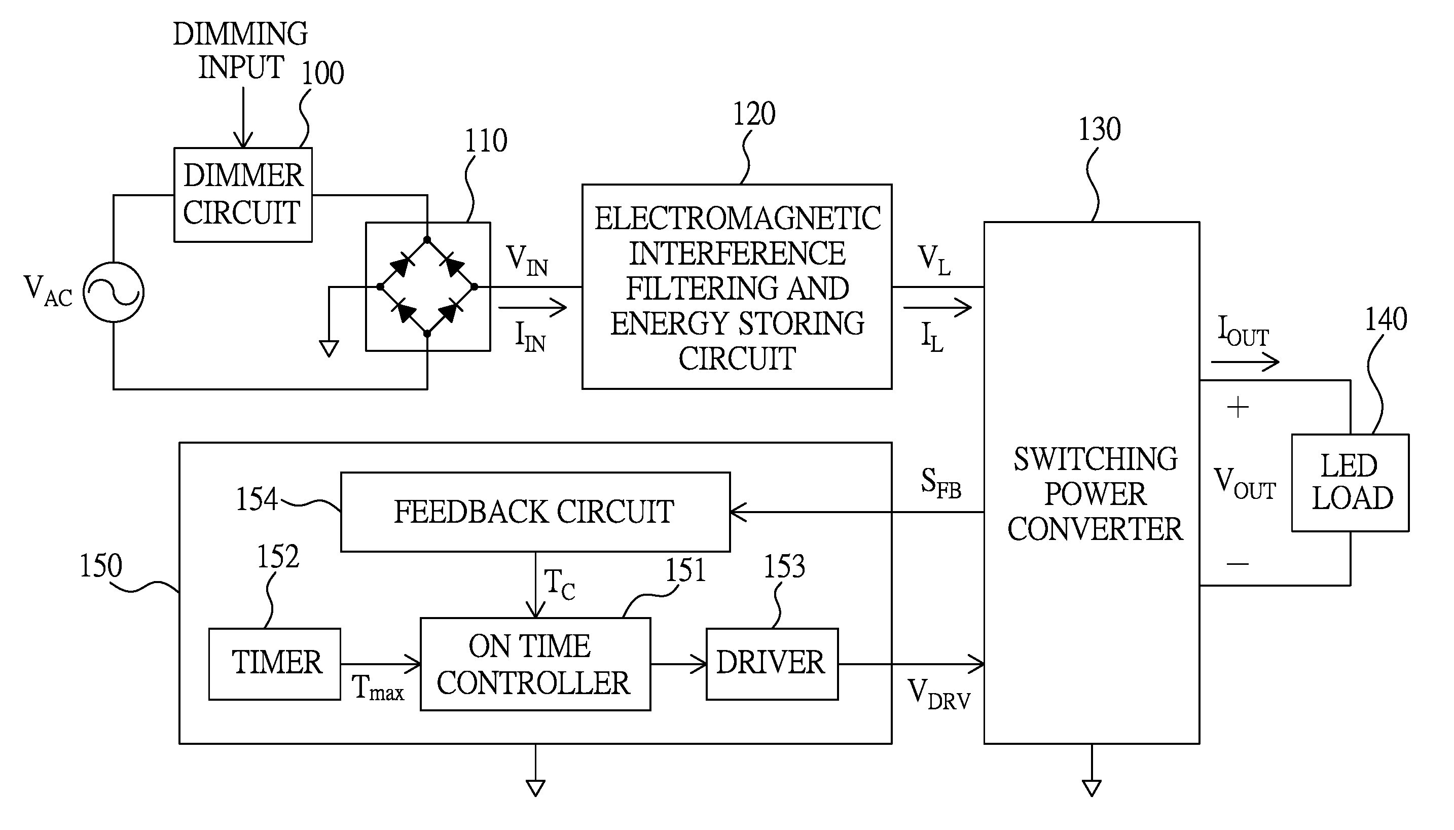
[0033]Please refer to FIG. 3, which illustrates a circuit diagram of a dimmable switching mode LED driving circuit according to an embodiment of the present invention. As illustrated in FIG. 3, the dimmable switching mode LED driving circuit includes a dimmer circuit 100, a bridge rectifier 110, an electromagnetic interference filtering and energy storing circuit 120, a switching power converter 130, an LED load 140, and a controller 150, the controller 150 including an on time controller 151, a timer 152, a driver 153, and a feedback circuit 154.

[0034]The dimmer circuit 100 is used for performing a phase-cutting operation on an AC voltage VAC to provide a phase-cut AC voltage in response to a dimming input. The phase-cutting operation can be a leading edge phase-cutting operation or a trailing edge phase-cutting operation.

[0035]The bridge rectifier 110 is used for providing an input voltage VIN by performing a rectifying operation on the phase-cut AC voltage.

[0036]The electromagnet...


PUM


Abstract

A dimmable switching mode LED driving circuit without phase angle measurement, including: a dimmer circuit for providing a phase-cut AC voltage; a bridge rectifier providing an input voltage by rectifying the phase-cut AC voltage; an electromagnetic interference filtering and energy storing circuit providing a line voltage according to the input voltage; a switching power converter converting the line voltage to an output current for an LED load under a control of a driving voltage; and a control unit using at least one feedback signal to perform a pulse width modulation operation to determine an on time for the switching voltage; wherein the control unit includes an on-time controller and a timer, the on-time controller determining the on time according to the at least one feedback signal, and the timer setting a maximum limit on the on time.

Description

BACKGROUND OF THE INVENTION[0001]1. Field of the Invention[0002]The present invention relates to a dimmable LED (light emitting diode) driving circuit, especially to a phase cut dimmable switching mode LED driving circuit without phase angle measurement.[0003]2. Description of the Related Art[0004]Conventional dimmable lighting circuits use a triac-based dimmer to perform a phase-cutting operation on a standard AC (alternating current) voltage source (60 Hz / 110 Vin North America or 50 Hz / 220 V in Europe) in response to a dimming operation, so as to control the input power and thereby control the lighting condition of a traditional lamp.[0005]Due to a longer lifespan and a better electrical efficiency, LED lamps have been gradually replacing traditional lamps. In applications where a traditional lamp is replaced with an LED lamp, apart from maintaining a good power factor, the driving circuit for the LED lamp is generally required to provide a constant output current to ensure a stab...

Claims


Application Information

Patent Timeline
Patent Type & Authority Patents(United States)
IPC IPC(8): H05B33/08H02M1/44H02M1/42H05B44/00
CPCH05B33/0815H05B33/0845H02M1/44H02M1/42H02M1/4225Y02B20/30Y02B70/10H05B45/3725H05B45/14
Inventor HUANG, WEN-HUNG
Owner ALITEK TECH
Why Eureka
Try Eureka