Stirring rotor for chemical engineering

A stirring rotor, chemical technology, applied in the directions of mixer accessories, mixers with rotating stirring devices, chemical instruments and methods, etc., can solve problems such as affecting processing work and inability to mix well, and achieve the effect of improving the stirring effect.

Inactive Publication Date: 2019-04-09
重庆伊莱卡实业有限公司
View PDF0 Cites 1 Cited by
  • Summary
  • Abstract
  • Description
  • Claims
  • Application Information

AI Technical Summary

Problems solved by technology

[0002] In the production process of chemical raw materials, it is necessary to stir and mix several different raw materials. At present, the stirring rotors commonly used are driven by the driving machine to carry out independent revolution or rotation to stir the chemical raw materials. If there are some high viscosity, For raw materials with low solubility, this kind of stirring rotor will stir the raw materials and rotate around the mixing drum, which cannot be mixed well, thus affecting the subsequent processing work

Method used


Image

  • Stirring rotor for chemical engineering

Examples


Embodiment

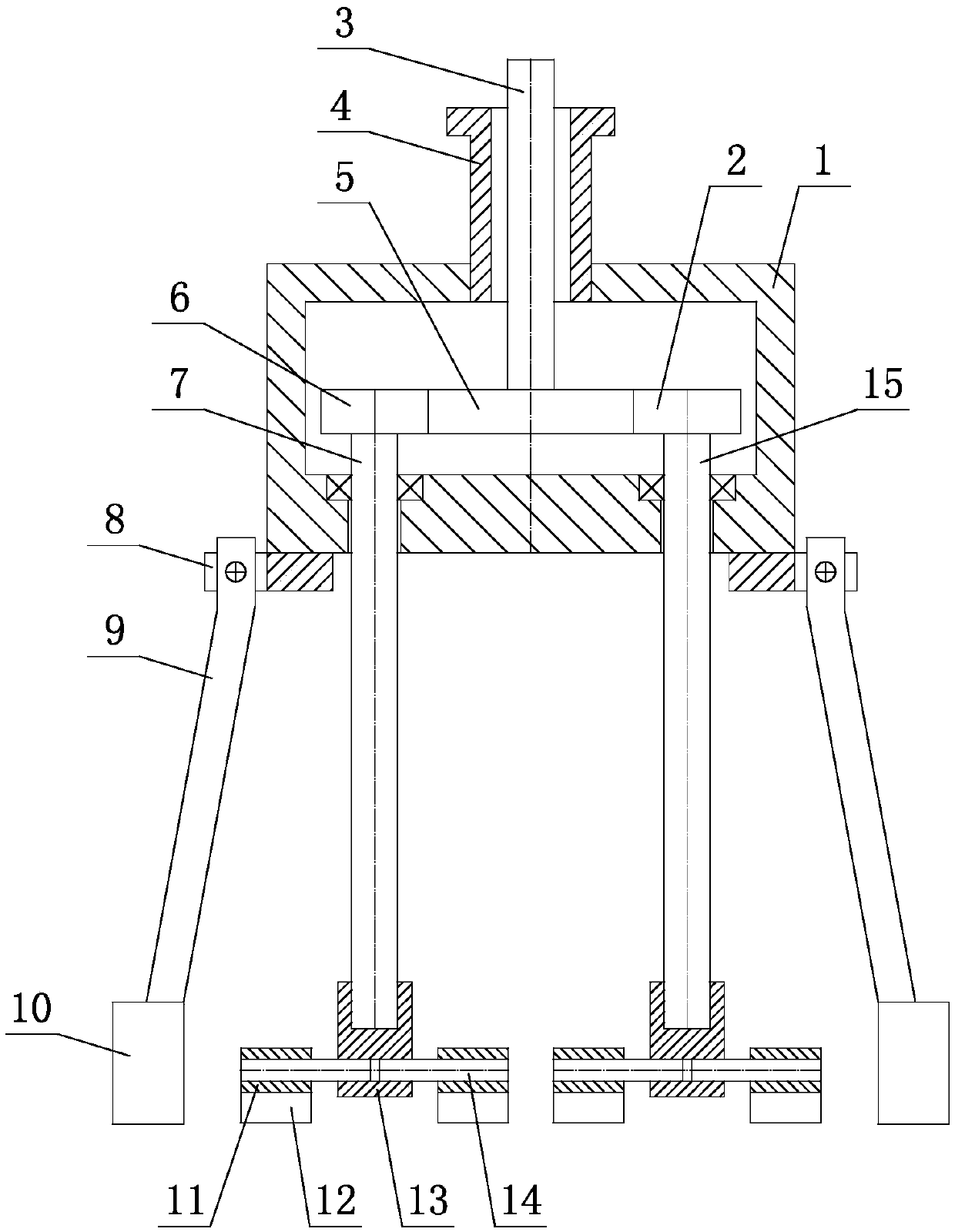
[0017] Such as figure 1 As shown, the agitating rotor used in the chemical industry includes a horizontally arranged casing 1, a sleeve 4 is vertically worn on the top of the casing 1, and a vertical shaft 3 is vertically installed in the sleeve 4. 1 The bottom of the inner vertical shaft 3 is fitted with a fixed gear 5, and a first rotating shaft 15 is installed vertically on the bottom of the box body 1. The first rotating shaft 15 is installed on the box body 1 through a bearing. The second rotating shaft 7 is vertically worn on the casing 1, and the second rotating shaft 7 is installed on the casing 1 through a bearing. Gear 2, on the second rotating shaft 7 in the box body 1, the second rotating gear 6 intermeshing with the fixed gear 5 is installed, and the stirring assembly is installed at the lower ends of the second rotating shaft 7 and the first rotating shaft 15 .

[0018] In this embodiment, the agitating assembly includes a vertical installation cover 13, horizon...


PUM


Abstract

The invention relates to a stirring rotor for chemical engineering, and belongs to the technical field of stirring rotors. The stirring rotor comprises a tank body which is horizontally arranged, a sleeve vertically runs through the top of the tank body, and a vertical shaft vertically runs through inside the sleeve; a fixed gear is arranged at the bottom of the vertical shaft in the tank body ina sleeving manner, and first rotating shaft vertically runs through the bottom of the tank body and is arranged on the tank body through a bearing; a second rotating shaft vertically runs through thetank body on the left side of the first rotating shaft and is arranged on the tank body through a bearing; a first rotary gear meshed with the fixed gear is arranged on the first rotating shaft in thetank body; a second rotary gear meshed with the fixed gear is arranged on the second rotating shaft in the tank body, and stirring components are arranged at lower ends of the first and second rotating shafts. According to the stirring rotor, rotation and revolution of the stirring components can be realized, and the stirring effect is improved.

Description

technical field [0001] The invention relates to a stirring rotor for chemical industry, belonging to the technical field of stirring rotors. Background technique [0002] In the production process of chemical raw materials, it is necessary to stir and mix several different raw materials. At present, the stirring rotors commonly used are driven by the driving machine to carry out independent revolution or rotation to stir the chemical raw materials. If there are some high viscosity, For raw materials with low solubility, this stirring rotor will stir the raw materials and rotate them around the mixing drum, which cannot be mixed well, thus affecting the subsequent processing work. Contents of the invention [0003] Based on the above deficiencies in the prior art, the technical problem to be solved by the present invention is: to provide a stirring rotor for chemical industry, which can rotate while revolving and improve the stirring effect. [0004] The agitating rotor fo...

Claims


Application Information

Patent Timeline
Patent Type & Authority Applications(China)
IPC IPC(8): B01F7/30B01F15/00
CPCB01F27/112B01F27/191B01F27/85B01F27/95B01F35/30
Inventor 刘斌
Owner 重庆伊莱卡实业有限公司
Why Eureka
Try Eureka