Cloth winding mechanism of cloth printing machine

A printing machine and cloth technology, which is applied in the direction of thin material processing, winding strips, sending objects, etc., can solve the problems of up and down shaking, wear between the cloth take-up roller and the support structures at both ends, and uneven cloth take-up, etc. Lifting, which is conducive to the effect of tidy collection and high production efficiency

Inactive Publication Date: 2019-04-09
苏州极数印花科技有限公司
View PDF7 Cites 2 Cited by
  • Summary
  • Abstract
  • Description
  • Claims
  • Application Information

AI Technical Summary

Problems solved by technology

The existing cloth receiving mechanism of the printing machine generally adopts a cloth receiving roller, which is driven by a motor to rotate and collect the cloth. As the weight of the cloth receiving roller increases, the problem of shaking up and down will occur during the rotation process, causing the cloth to be collected unevenly. , also accelerates the wear between the delivery roller and the support structures at both ends

Method used


Image

  • Cloth winding mechanism of cloth printing machine
  • Cloth winding mechanism of cloth printing machine
  • Cloth winding mechanism of cloth printing machine

Examples


Embodiment Construction

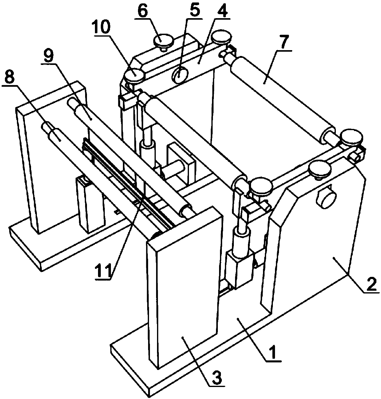
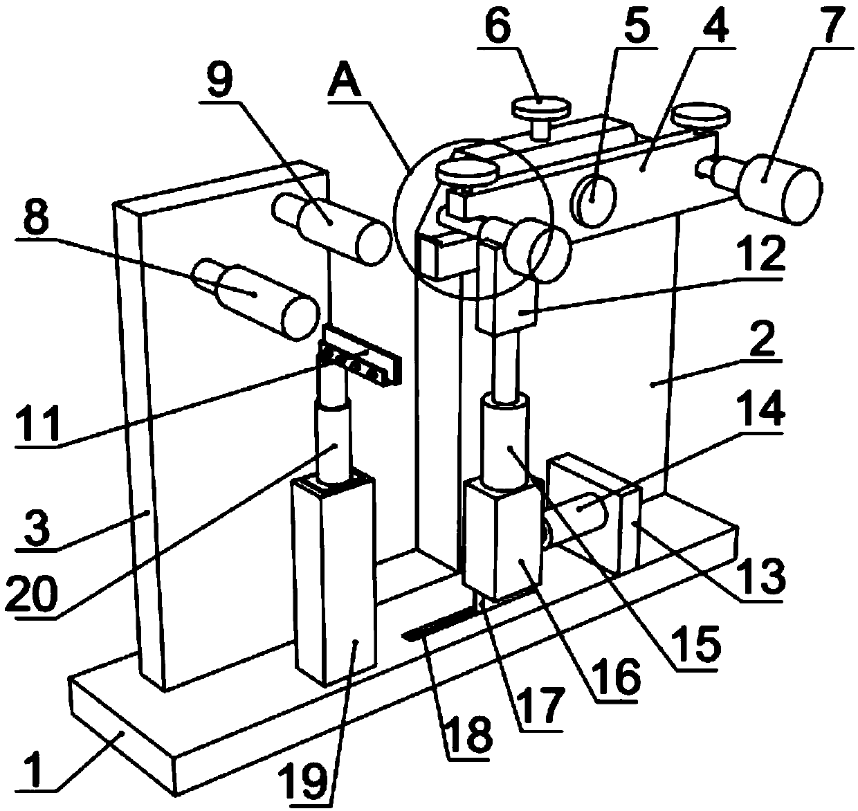
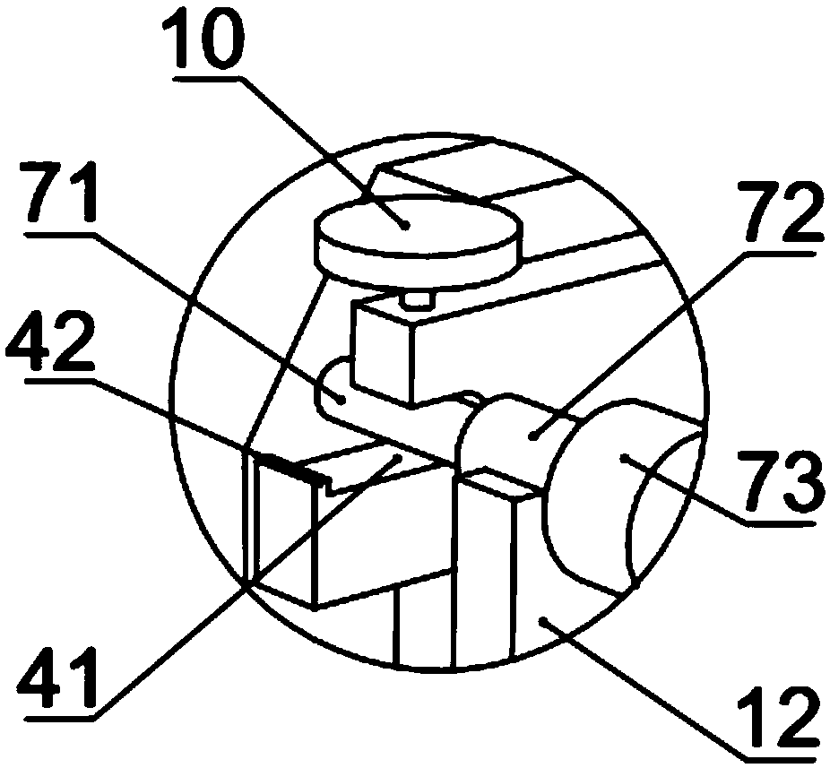
[0024] like Figure 1 to Figure 5 As shown, a cloth receiving mechanism of a cloth printing machine includes a base 1, a pair of first supporting boards 2 arranged above the base 1, and two cloth receiving rollers 7 arranged between the first supporting boards 2, and the cloth receiving rollers 7 includes a cloth receiving shaft 73, a support shaft 72 connected to both ends of the cloth receiving shaft 73, and a fixed shaft 71 connected to the support shaft 72; The first fastening bolt 6 of the rotating shaft 5, the rotating shaft 5 is fixedly connected with the support plate 4, and both ends of the support plate 4 are provided with a transverse U-shaped fixing groove 41, and a fixing shaft 71 is installed in the fixing groove 41, and the fixing groove 41 above The second fastening bolt 10 for fixing the fixed shaft 71 is provided, and the end of the fixed groove 41 is provided with a stopper 42, which can prevent the cloth receiving roller from rolling off during the replacem...


PUM


Abstract

The invention provides a cloth winding mechanism of a cloth printing machine, and belongs to the technical field of printing machines. The cloth winding mechanism includes a base, a pair of first supporting plates arranged at the upper portion of the base and two cloth winding rollers arranged between the first supporting plates, each cloth winding roller comprises a cloth winding shaft, a supporting shaft connected to both ends of the cloth winding shaft and a fixing shaft connected to the supporting shaft, rotating shafts are arranged at the upper portions of the first supporting plates in apenetrating mode, first fastening bolts for fixing the rotating shafts are arranged at the tops of the first supporting plates, and supporting plates are fixedly connected with the rotating shafts; and transverse U-shaped fixing grooves are formed in the two ends of each supporting plate, the fixing shafts are mounted in the fixing grooves, second fastening bolts for fixing the fixing shafts arearranged above the fixing grooves, sliding seats are further arranged on the base, first vertical hydraulic cylinders are arranged at the upper parts of the sidling seats, the top ends of the first vertical hydraulic cylinders are connected with supporting blocks, and damping grooves matched with the supporting shafts in a clamped mode are formed in the supporting blocks. The cloth winding mechanism can support the cloth winding rollers and prevent the cloth winding rollers from shaking up and down, the two end wear is small, the cloth winding is neat, and the long time stopping for replacingthe cloth winding rollers does not need.

Description

technical field [0001] The invention belongs to the technical field of printing machines, and in particular relates to a cloth receiving mechanism of a cloth printing machine. Background technique [0002] The printing machine is suitable for printing on various materials. Thermal transfer printing can be used for the printing process of fabrics. Its working principle is: before transferring printing on cloth, clothing, and ready-made garments, first use sublimation dye ink to print on specific printing paper with printing machinery to become transfer printing paper, and then print The patterned side of the paper sticks to the fabric and enters the transfer printing machine after heating and pressure, so that the sublimation dye ink on the transfer printing paper is vaporized and then transferred to the fabric. The existing cloth receiving mechanism of the printing machine generally adopts a cloth receiving roller, which is driven by a motor to rotate and collect the cloth....

Claims


Application Information

Patent Timeline
Patent Type & Authority Applications(China)
IPC IPC(8): B65H19/30B65H23/032B65H23/26B65H35/06
CPCB65H19/30B65H23/032B65H23/26B65H35/06B65H2701/1133
Inventor 王文礼徐俊
Owner 苏州极数印花科技有限公司
Why Eureka
Try Eureka