A gantry type intelligent burner for a chip

A gantry-type, burning machine technology, applied in the direction of software deployment, etc., can solve problems such as low work efficiency, complex structure, and many processes, and achieve the effect of improving accuracy, high accuracy, and ensuring accuracy

Inactive Publication Date: 2019-04-09
苏州永创智能科技有限公司
View PDF4 Cites 2 Cited by
  • Summary
  • Abstract
  • Description
  • Claims
  • Application Information

AI Technical Summary

Problems solved by technology

Existing chip programming is done manually or through a programming device, but the structure of the current chip programming device is

Method used


Image

  • A gantry type intelligent burner for a chip
  • A gantry type intelligent burner for a chip
  • A gantry type intelligent burner for a chip

Examples


Embodiment 1

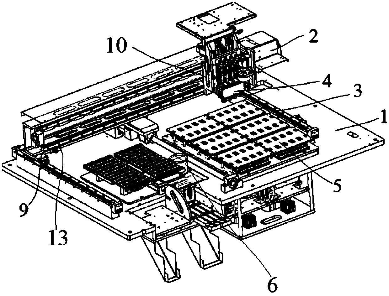
[0043] Embodiment 1: A gantry-type intelligent burner for chips, including a substrate 1, an X-axis drive mechanism 2, a Y-axis drive mechanism 3, a suction mechanism 4 and a burner mechanism 5, and the Y-axis drive mechanism 3 Set on the upper surface of the substrate 1, the X-axis driving mechanism 2 is installed and connected with the Y-axis driving mechanism 3 through several XY connecting blocks 9 and can reciprocate in the Y-axis direction, and the suction mechanism 4 moves through the XZ connecting blocks 10 Installed on the X-axis drive mechanism 2 and capable of reciprocating movement along the X-axis direction, the burning mechanism 5 is installed on the substrate 1 and located below the suction mechanism 4;

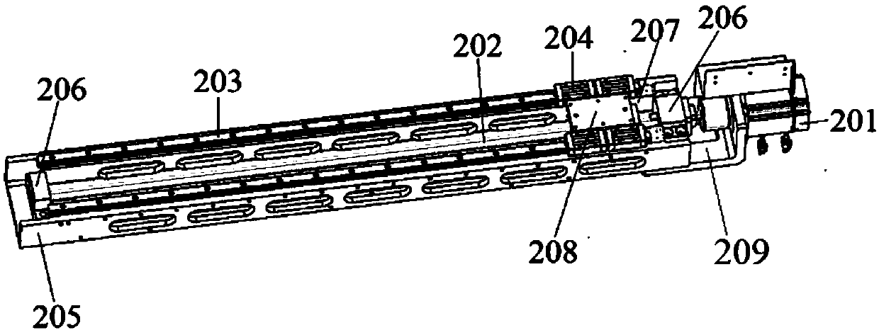
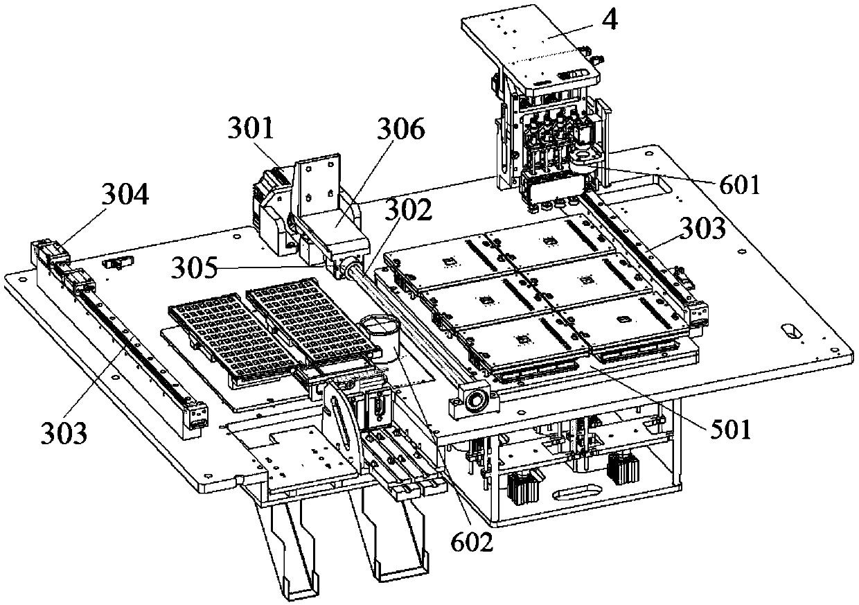
[0044] The Y-axis drive mechanism 3 further includes a Y-axis motor 301, a Y-axis screw 302 connected to the Y-axis motor 301, at least one Y-axis slide rail 303, and several Y-axis sliders movably mounted on the Y-axis slide rail 303 304, the X-axis driving me...

Embodiment 2

[0057] Embodiment 2: A gantry-type intelligent burner for chips, including a substrate 1, an X-axis drive mechanism 2, a Y-axis drive mechanism 3, a suction mechanism 4 and a burner mechanism 5, and the Y-axis drive mechanism 3 Set on the upper surface of the substrate 1, the X-axis driving mechanism 2 is installed and connected with the Y-axis driving mechanism 3 through several XY connecting blocks 9 and can reciprocate in the Y-axis direction, and the suction mechanism 4 moves through the XZ connecting blocks 10 Installed on the X-axis drive mechanism 2 and capable of reciprocating movement along the X-axis direction, the burning mechanism 5 is installed on the substrate 1 and located below the suction mechanism 4;

[0058] The Y-axis drive mechanism 3 further includes a Y-axis motor 301, a Y-axis screw 302 connected to the Y-axis motor 301, at least one Y-axis slide rail 303, and several Y-axis sliders movably mounted on the Y-axis slide rail 303 304, the X-axis driving me...


PUM


Abstract

The invention discloses a gantry type intelligent burner for a chip, which includes a substrate, an X-axis driving mechanism, a Y-axis driving mechanism, a suction mechanism and a burning mechanism; the Y-axis driving mechanism is arranged on the upper surface of the base plate; the X-axis driving mechanism is mounted and connected with the Y-axis driving mechanism through a plurality of XY connecting blocks and can reciprocate in the Y-axis direction; The burning mechanism is installed on the substrate and located below the material suction mechanism. a limiting bracket is also arranged; Thelimiting support is fixedly installed on the lower portion of the front side face of the installation plate, the suction rod is connected with an upper plate of the limiting support through a drivingspline, the calibration mechanism further comprises an upper camera and a lower camera, the upper camera is installed on the material suction mechanism, and the lower camera is installed on the base plate and arranged opposite to the upper camera. The position of the chip in the X/Y axis and the circumferential direction can be calibrated and corrected, the accuracy of the position of the chip placed in the burning base is guaranteed, and therefore high-precision burning of the precise chip is achieved.

Description

technical field [0001] The invention relates to the technical field of chip programming, in particular to a gantry-type intelligent programming machine for chips. Background technique [0002] Chips are currently more commonly used electronic components in the electronics industry, and there are multiple production processes for them. Burning is one of the processes in chip manufacturing. When burning, it is necessary to control the burning point. Therefore, in the process of chip burning, there is a high requirement for the position accuracy of the chip placement. Existing chip programming is done manually or by a programming device, but the structure of the current chip programming device is relatively complicated and there are many processes, and still requires more manpower to participate, and the work efficiency is low. Contents of the invention [0003] The object of the present invention is to provide a gantry-type intelligent programming machine for chips, which c...

Claims


Application Information

Patent Timeline
IPC IPC(8): G06F8/61
CPCG06F8/63
Inventor 桂义勇曹杰
Owner 苏州永创智能科技有限公司
Why Eureka
Try Eureka