Eureka AIR delivers breakthrough ideas for toughest innovation challenges, trusted by R&D personnel around the world.

Display panel and display device

A display panel and display area technology, applied in static indicators, instruments, etc., can solve the problems of limited process capability, incident light stray light, etc., to reduce the non-display area, ensure the fineness, and improve the display effect.

Active Publication Date: 2019-04-09
KUNSHAN GO VISIONOX OPTO ELECTRONICS CO LTD
View PDF5 Cites 21 Cited by
  • Summary
  • Abstract
  • Description
  • Claims
  • Application Information

AI Technical Summary

Problems solved by technology

[0003] In the full-screen display technology, it is necessary to remove the non-display area of ​​the display panel as much as possible. However, the existing technology is limited by the process capability, and the non-display area needs to be reserved for the installation of photosensitive modules such as cameras.
If the camera and other photosensitive modules are placed under the display panel, the incident light will cause stray light due to the diffraction of the metal traces in the display panel.

Method used


Image

  • Display panel and display device
  • Display panel and display device
  • Display panel and display device

Examples


Embodiment Construction

[0025] The characteristics and exemplary embodiments of various aspects of the present invention will be described in detail below. In order to make the purpose, technical solutions and advantages of the present invention clearer, the present invention will be further described in detail below in conjunction with the accompanying drawings and specific embodiments. It should be understood that the specific embodiments described here are only configured to explain the present invention, not to limit the present invention. It will be apparent to one skilled in the art that the present invention may be practiced without some of these specific details. The following description of the embodiments is only to provide a better understanding of the present invention by showing examples of the present invention.

[0026] It should be noted that in this article, relational terms such as first and second are only used to distinguish one entity or operation from another entity or operation...


PUM


Abstract

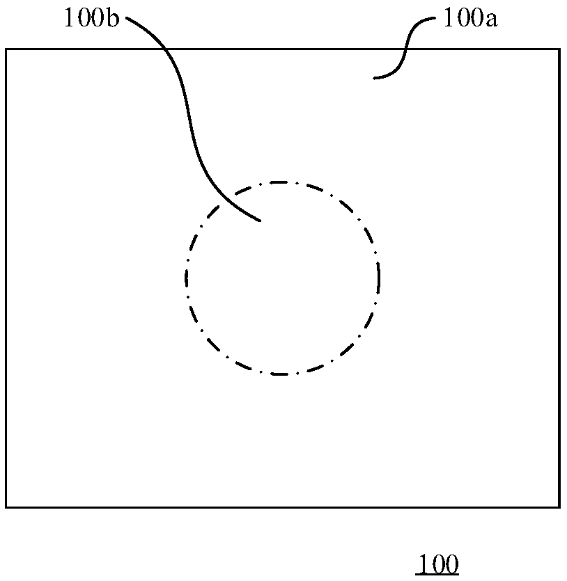
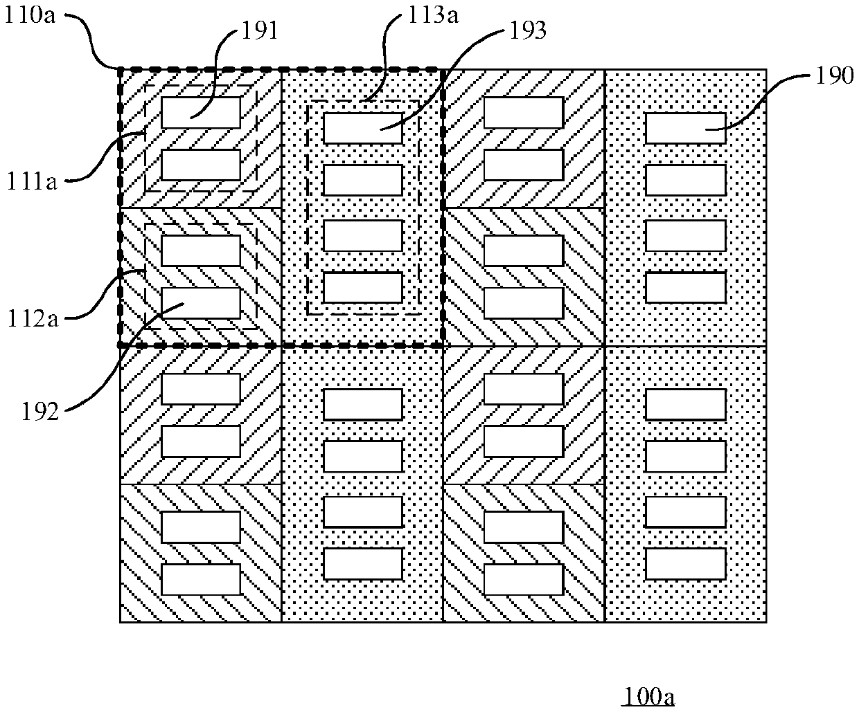
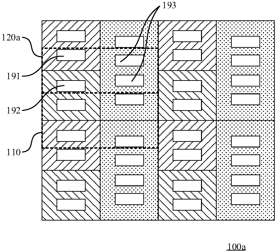
The invention discloses a display panel and a display device, and the display panel comprises a first display area which comprises a plurality of first repeating units arranged in an array; a second display area which comprises a plurality of second repeating units arranged in an array mode, wherein the first repeating units and the second repeating units each comprise a plurality of sub-pixels, the density of the sub-pixels of the second display area is smaller than that of the sub-pixels of the first display area, and the second repeating units and the first repeating units are the same in outline shape. According to the display panel provided by the embodiment of the invention, the pixel density of the second display areas is relatively reduced, so that the array wiring in the second display area is reduced, the diffraction phenomenon of the wiring to incident light is reduced, the integration of the photosensitive module at the second display area is facilitated, and the non-display area of the display panel is reduced. The second repeating units and the first repeating units are the same in outline shape, so that the sub-pixels in the first display area and the sub-pixels in the second display area can be formed by using the same mask plate, and the design cost is reduced.

Description

technical field [0001] The present invention relates to the display field, in particular to a display panel and a display device. Background technique [0002] In the field of display, full-screen display technology has gradually become the mainstream, and this technology is very helpful for improving the screen-to-body ratio of terminal devices such as mobile phones. [0003] In the full-screen display technology, it is necessary to remove the non-display area of ​​the display panel as much as possible. However, the existing technology is limited by the process capability, and it is necessary to reserve the non-display area for the installation of photosensitive modules such as cameras. If a photosensitive module such as a camera is arranged under the screen body of the display panel, incident light will cause stray light due to diffraction of metal traces in the display panel. Contents of the invention [0004] The invention provides a display panel and a display device...

Claims


Application Information

Patent Timeline
Patent Type & Authority Applications(China)
IPC IPC(8): G09G3/20
CPCG09G3/2074G09G3/3208
Inventor 余珺
Owner KUNSHAN GO VISIONOX OPTO ELECTRONICS CO LTD
Why Eureka
Eureka Blog
Learn More