
Stirring device used in synthetic resin production process

A production process and synthetic resin technology, applied to mixers with rotating stirring devices, mixer accessories, chemical/physical processes, etc., can solve problems such as poor user experience, easily damaged wires, and inconvenience for users to discharge materials, and achieve Easy to repair wires, easy to discharge the effect

Inactive Publication Date: 2019-04-12
浙江离火新材料科技有限公司
View PDF5 Cites 1 Cited by
  • Summary
  • Abstract
  • Description
  • Claims
  • Application Information

AI Technical Summary

Problems solved by technology

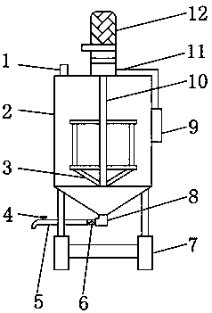
[0002] With the development of synthetic technology, synthetic materials are more and more widely used in life, especially synthetic resin. The more synthetic materials are used, the more demand will be in production. In the process of producing synthetic resin It is necessary to use a stirring device to stir the materials so that the raw materials can be fully and evenly mixed together so that the production process can reach the standard. There are many types of stirring devices, but the existing stirring devices cannot adjust the discharge pipe when in use. The height of the discharge end is inconvenient for users to discharge, and the discharge speed cannot be changed, and the wires cannot be protected. The wires are easily damaged when exposed to the outside for a long time, which makes the user experience of the device poor.

Method used


Image

  • Stirring device used in synthetic resin production process
  • Stirring device used in synthetic resin production process
  • Stirring device used in synthetic resin production process

Examples


Embodiment Construction

[0022] The following will clearly and completely describe the technical solutions in the embodiments of the present invention with reference to the accompanying drawings in the embodiments of the present invention. Obviously, the described embodiments are only some, not all, embodiments of the present invention. Based on the embodiments of the present invention, all other embodiments obtained by persons of ordinary skill in the art without making creative efforts belong to the protection scope of the present invention.

[0023] In the description of the present invention, it should be noted that the terms "upper", "lower", "inner", "outer", "front end", "rear end", "both ends", "one end", "another end" The orientation or positional relationship indicated by etc. is based on the orientation or positional relationship shown in the drawings, and is only for the convenience of describing the present invention and simplifying the description, rather than indicating or implying that ...


PUM


Abstract

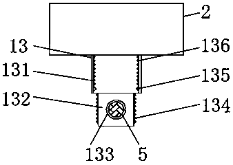
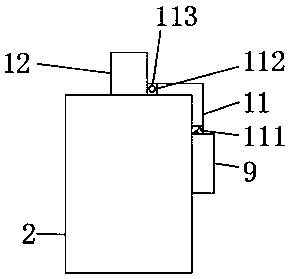
The invention discloses a stirring device used in a synthetic resin production process. The stirring device comprises a device body; a motor is fixedly arranged at the middle part of the outer surfaceof the upper end of the device body; a wire shielding box is movably arranged on the outer surface of one side of the motor; a material injection port is fixedly arranged on the outer surface of theupper end of the device body and is close to the edge; a rotating shaft is movably arranged in the device body; spiral blades are fixedly arranged on the outer surface of the rotating shaft; a supporting frame is fixedly arranged under the outer surface of the lower end of the device body; a connecting head is fixedly arranged at the middle position of the outer surface of the lower end of the device body; and a universal pipe is fixedly arranged on the outer surface of one side of the connecting head. According to the stirring device, through the arrangement of a series of the structures, theheight of the outlet end of a discharging pipe can be adjusted in a using process of the device, so that the synthetic resin can be conveniently discharged; the discharging speed can be controlled bychanging the height; and electric wires of the stirring device can be protected, so that damage caused by the fact that the electric wires are exposed to the outside can be avoided.

Description

technical field [0001] The invention relates to the technical field of stirring devices, in particular to a stirring device used in the production process of synthetic resin. Background technique [0002] With the development of synthetic technology, synthetic materials are more and more widely used in life, especially synthetic resin. The more synthetic materials are used, the more demand will be in production. In the process of producing synthetic resin It is necessary to use a stirring device to stir the materials so that the raw materials can be fully and evenly mixed together so that the production process can reach the standard. There are many types of stirring devices, but the existing stirring devices cannot adjust the discharge pipe when in use. The height of the discharge end is inconvenient for the user to discharge, and the discharge speed cannot be changed, and the wires cannot be protected. The wires are easily damaged when exposed to the outside for a long tim...

Claims


Application Information

Patent Timeline
IPC IPC(8): B01F7/18B01F15/00
CPCB01F27/90B01F35/10B01F35/75B01F2101/2805
Inventor 刘树宁王云平
Owner 浙江离火新材料科技有限公司
Learn More