Impurity removal device for peanuts

A technology for removing impurities and peanuts, applied in the direction of solid separation, sieve, grid, etc., can solve the problems of arm soreness, limited sieve capacity, time-consuming and labor-intensive, etc., to achieve the effect of labor-saving screening

Inactive Publication Date: 2019-04-12
肖明香
View PDF0 Cites 2 Cited by
  • Summary
  • Abstract
  • Description
  • Claims
  • Application Information

AI Technical Summary

Problems solved by technology

[0003] In order to overcome the limited capacity of the sieve, when using a sieve to remove impurities in a

Method used


Image

  • Impurity removal device for peanuts
  • Impurity removal device for peanuts
  • Impurity removal device for peanuts

Examples


Example Embodiment

[0019] Example 1

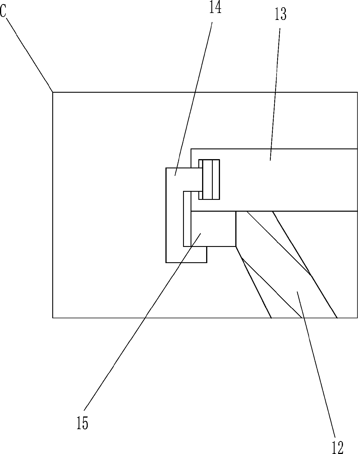
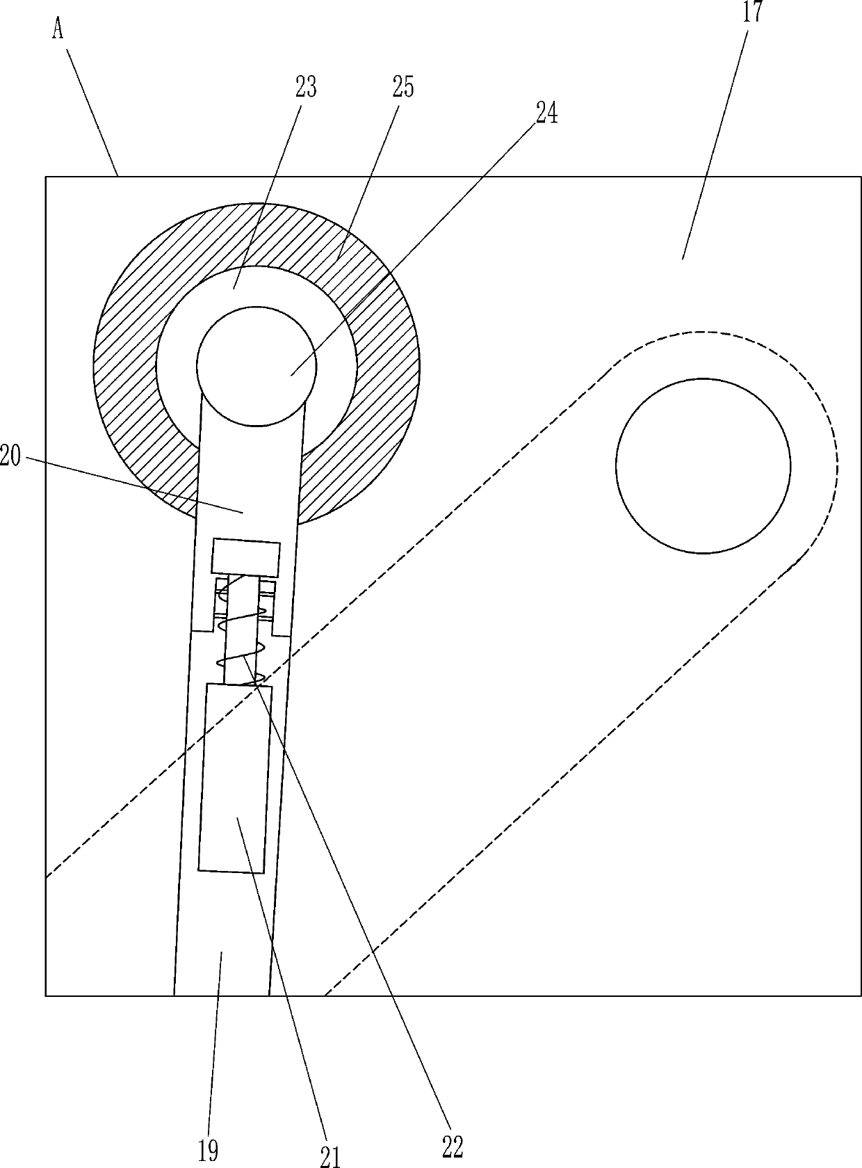
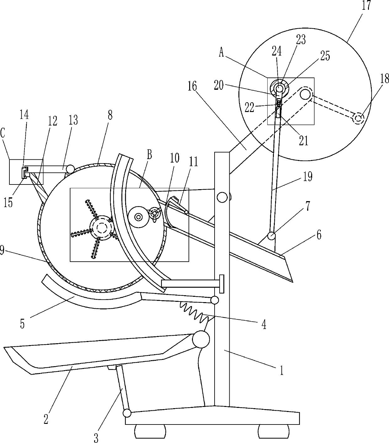
[0020] A peanut impurity removal device, such as Figure 1-4 As shown, it includes a bracket 1, a collection frame 2, a first rotating rod 3, a first spring 4, a rotating plate 5, a funnel 6, a first handle 7, a placing frame 8, a screen 9, a second rotating rod 11, and a feed The bucket 12, the cover 13, the third rotating rod 14 and the blocking rod 15. The lower part of the bracket 1 is provided with a collection frame 2 that can rotate on the left side. The inner bottom of the bracket 1 is provided with a first rotary rod 3 on the left side. 3 The top end is in contact with the bottom of the collection frame 2, a rotating plate 5 is provided on the left side of the middle of the bracket 1, a first spring 4 is connected to the right side of the bottom of the rotating plate 5, and the bottom end of the first spring 4 is connected to the lower left side of the bracket 1. A spring 4 is located above the collection frame 2, a funnel 6 is pivotally connected to ...

Example Embodiment

[0021] Example 2

[0022] A peanut impurity removal device, such as Figure 1-4 As shown, it includes a bracket 1, a collection frame 2, a first rotating rod 3, a first spring 4, a rotating plate 5, a funnel 6, a first handle 7, a placing frame 8, a screen 9, a second rotating rod 11, and a feed The bucket 12, the cover 13, the third rotating rod 14 and the blocking lever 15. The lower part of the bracket 1 is provided with a collection frame 2 that can rotate on the left side, and the inner bottom of the bracket 1 is provided with a first rotary rod 3 on the left side. 3 The top end is in contact with the bottom of the collection frame 2, a rotating plate 5 is provided on the left side of the middle of the bracket 1, a first spring 4 is connected to the right side of the bottom of the rotating plate 5, and the bottom end of the first spring 4 is connected to the lower left side of the bracket 1. A spring 4 is located above the collection frame 2, a funnel 6 is pivotally connect...

Example Embodiment

[0024] Example 3

[0025] A peanut impurity removal device, such as Figure 1-4 As shown, it includes a bracket 1, a collection frame 2, a first rotating rod 3, a first spring 4, a rotating plate 5, a funnel 6, a first handle 7, a placing frame 8, a screen 9, a second rotating rod 11, and a feed The bucket 12, the cover 13, the third rotating rod 14 and the blocking lever 15. The lower part of the bracket 1 is provided with a collection frame 2 that can rotate on the left side, and the inner bottom of the bracket 1 is provided with a first rotary rod 3 on the left side. 3 The top end is in contact with the bottom of the collection frame 2, a rotating plate 5 is provided on the left side of the middle of the bracket 1, a first spring 4 is connected to the right side of the bottom of the rotating plate 5, and the bottom end of the first spring 4 is connected to the lower left side of the bracket 1. A spring 4 is located above the collection frame 2, a funnel 6 is pivotally connect...


PUM


Abstract

The invention relates to an impurity removal device, in particular to an impurity removal device for peanuts, and aims to provide the impurity removal device for the peanuts. The device has the advantages of high capacity and convenience in impurity removal by people. The impurity removal device for the peanuts adopts the technical scheme that the impurity removal device comprises a bracket, a collecting frame, a first rotating rod, a first spring, a rotating plate, a funnel, a first handle, a placing frame, a screen, a second rotating rod and the like, wherein the collecting frame is rotatably arranged on the left side of the lower part of the bracket, the first rotating rod is rotatably arranged on the left side of the inner bottom of the bracket, the top end of the first rotating rod makes contact with the bottom of the collecting frame, the rotating plate is rotatably arranged on the left side of the middle of the bracket, and the first spring is connected to the right side of thebottom of the rotating plate. According to the impurity removal device, the impurity removal operation can be performed on a large quantity of peanuts by virtue of the placing frame; the peanuts can be screened with labor saving by rotating a second handle, so that arms of people cannot ache; and the peanuts in the placing frame can be mixed by virtue of a sixth rotating rod, so that impurities are screened by the screen.

Description

technical field [0001] The invention relates to a device for removing impurities, in particular to a device for removing impurities for peanuts. Background technique [0002] When people shell the peanuts, some impurities will remain in the peanuts. At this time, people will pour the peanuts that need to be removed into the sieve, and then shake the sieve repeatedly, so that the impurities are sieved out of the sieve, so that the impurities are removed. Out of the peanuts, due to the limited capacity of the sieve, too many peanuts cannot be filled at one time. When there are many peanuts, people need to pour the peanuts into the sieve in batches, and then shake the sieve repeatedly to remove impurities, but this will make people's arms It will be sore and time consuming. Contents of the invention [0003] In order to overcome the limited capacity of the sieve, when using a sieve to remove impurities in a large number of peanuts, people's arms will feel sore, time-consumin...

Claims


Application Information

Patent Timeline
IPC IPC(8): B07B1/24B07B1/42B07B1/46
CPCB07B1/24B07B1/42B07B1/46
Inventor 肖明香
Owner 肖明香
Why Eureka
Try Eureka