Test tube cleaning device for urology department

A cleaning device and urology technology, applied in the field of medical supplies, can solve the problems of water splashing, easy collision with each other, time-consuming and labor-intensive, etc., and achieve the effect of convenient cleaning, stable structure, convenient and quick operation

Inactive Publication Date: 2019-04-12
NANYANG CITY CENT HOSPITAL
View PDF7 Cites 10 Cited by
  • Summary
  • Abstract
  • Description
  • Claims
  • Application Information

AI Technical Summary

Problems solved by technology

[0002] With the use of a large number of test tubes in the urology department, it takes a lot of manpower to clean these test tubes every day. At present, the cleaning of the test tubes in the urology department is usually done manually one by one. It is also easy to collide with each other and cause the test tube to break, there is a certain danger, and it is not suitable for cleaning a large number of test tubes
[0003] Although the existing urological test tube cleaning device can realize the large-scale cleaning operation of test tubes, it is easy to cause water splashing during the cleaning process and lacks necessary cleaning equipment for the box body. At the same time, its test tube brush The separate design of the water spray assembly cannot make the brushing effect better, and it does not have the operation of automatic ejection of the test tube and automatic test tube brush, which affects the operation of putting in and taking out the test tube; A test tube cleaning device designed to solve the above problems

Method used


Image

  • Test tube cleaning device for urology department
  • Test tube cleaning device for urology department

Examples


Embodiment 1

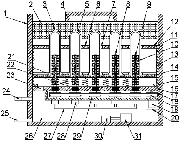
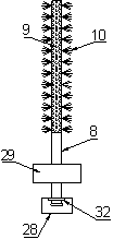
[0023] see Figure 1 ~ Figure 2 , in this embodiment, a test tube cleaning device for urology, comprising a cleaning box 1, a counterweight gland 2, a cleaning rod 8, a bearing plate 14 and a partition plate 16, the bottom of the cleaning box 1 is internally fixed Dividing plate 16 is arranged, and the bottom of dividing plate 16 is set as reservoir 26, and the side of reservoir 26 is connected with water inlet pipe 24 and drain pipe 25, and valve is all installed on water inlet pipe 24 and drain pipe 25, and drain pipe 25 is installed on Clean the bottom side of the casing 1 to facilitate the injection or discharge of water in the reservoir 26 through the water inlet pipe 24 and the drain pipe 25; a water pump 31 is installed at the bottom of the reservoir 26, and the water inlet end of the water pump 31 is connected to a filter 30, The water outlet end of the water pump 31 is connected to the diversion joint 28 , the diversion joint 28 is fixed on the bottom of the transmiss...

Embodiment 2

[0030] see Figure 1 ~ Figure 2 , in this embodiment, a urology test tube cleaning device, in this embodiment, inject disinfectant into the reservoir 26, and realize disinfection treatment while cleaning the test tube body 5, the urology test tube cleaning The structure of the device is the same as in Example 1.


PUM


Abstract

The invention discloses a test tube cleaning device for the urology department, belongs to the field of medical supplies and solves the problem that test tube crushing is easily caused as an existingurology department test tube needs to manually brush and clean, wastes time and labour and is low in cleaning efficiency. According to the technical scheme, the key point is that the test tube cleaning device comprises a cleaning box body, a counterweight pressure cover, a cleaning rod, a bearing plate and a separating plate, wherein the separating plate is fixedly arranged inside the bottom end of the cleaning box body; a water storage tank is arranged on the bottom of the separating plate; under starting of a water pump and a motor, water in the water storage tank is pumped into the cleaningrod and is sprayed out from water spraying holes, and is matched with bristles to co-rotate for conveniently cleaning a test tube; under applied pressure of the counterweight pressure cover, the testtube body presses a bearing plate compression spring and downwards moves along slide rails until the test tube body is arranged on the cleaning rod in a sleeving mode; when the cleaning rod rotates,the water spraying holes spray water and the water is matched with the bristles to clean the inner wall of the test tube body, so that operations are convenient and quick; and cleaning water flows into the water storage tank along a reflow hole, so that cyclic utilization of water resources is realized.

Description

technical field [0001] The invention relates to the field of medical supplies, in particular to a test tube cleaning device for urology. Background technique [0002] With the use of a large number of test tubes in the urology department, it takes a lot of manpower to clean these test tubes every day. At present, the cleaning of the test tubes in the urology department is usually done manually one by one. It is also easy to collide with each other and cause the test tube to break, which has certain dangers and is not suitable for cleaning a large number of test tubes. [0003] Although the existing urological test tube cleaning device can realize the large-scale cleaning operation of test tubes, it is easy to cause water splashing during the cleaning process and lacks necessary cleaning equipment for the box body. At the same time, its test tube brush The separate design of the water spray assembly cannot make the brushing effect better, and it does not have the operation o...

Claims


Application Information

Patent Timeline
Patent Type & Authority Applications(China)
IPC IPC(8): B08B9/08B08B9/34B08B9/36B08B9/42
CPCB08B9/0808B08B9/0813B08B9/0856B08B9/34B08B9/36B08B9/42
Inventor 胡跃世
Owner NANYANG CITY CENT HOSPITAL
Why Eureka
Try Eureka