Nailing gun

A nailing gun and housing technology, applied in the field of nailing guns, can solve the problems of locking failure, the impact of the service life of the nailing machine, and the unsuitable design of the slot is too deep, so as to avoid locking failure, improve service life, and reduce wear and tear. Effect

Pending Publication Date: 2019-04-12
TAIZHOU DINGBA POWER TOOLS
View PDF12 Cites 5 Cited by
  • Summary
  • Abstract
  • Description
  • Claims
  • Application Information

AI Technical Summary

Problems solved by technology

[0004] However, the analysis of the above-mentioned patent documents shows that when the motor touches the clip to unlock the striker, at this time, the striker is pushed by the air pressure to form a large friction between the clip and the clip during the unlocking process, which leads to The contact position between the clip and the striker is prone to wear and is affected by the width of the striker. The groove here should not be designed too deep. Therefore, after the existing nailing machine has been used for a period of time, the problem of locking failure is prone to occur, resulting in The nailing machine needs to be repaired to replace parts such as clips and firing pins, or even be scrapped directly. That is to say, the above factors have a serious impact on the service life of the nailing machine

Method used


Image

  • Nailing gun
  • Nailing gun
  • Nailing gun

Examples


Embodiment 1

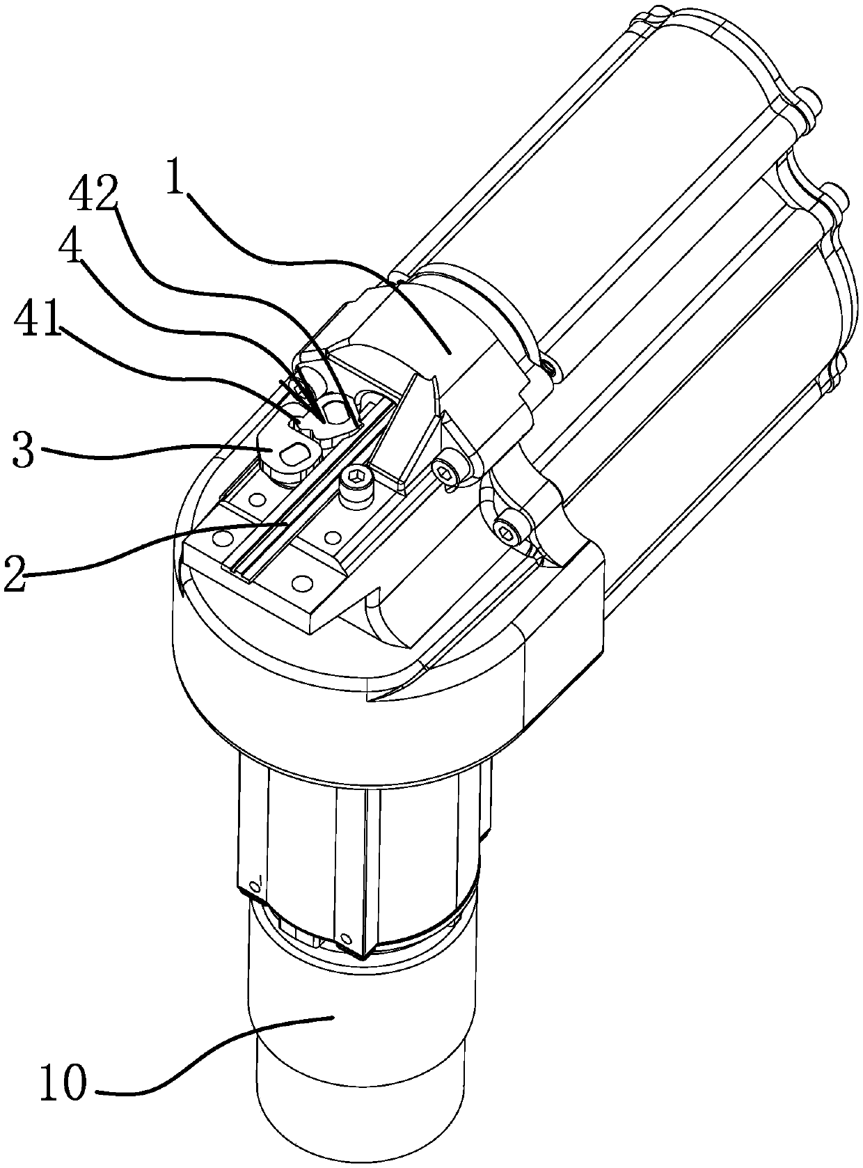
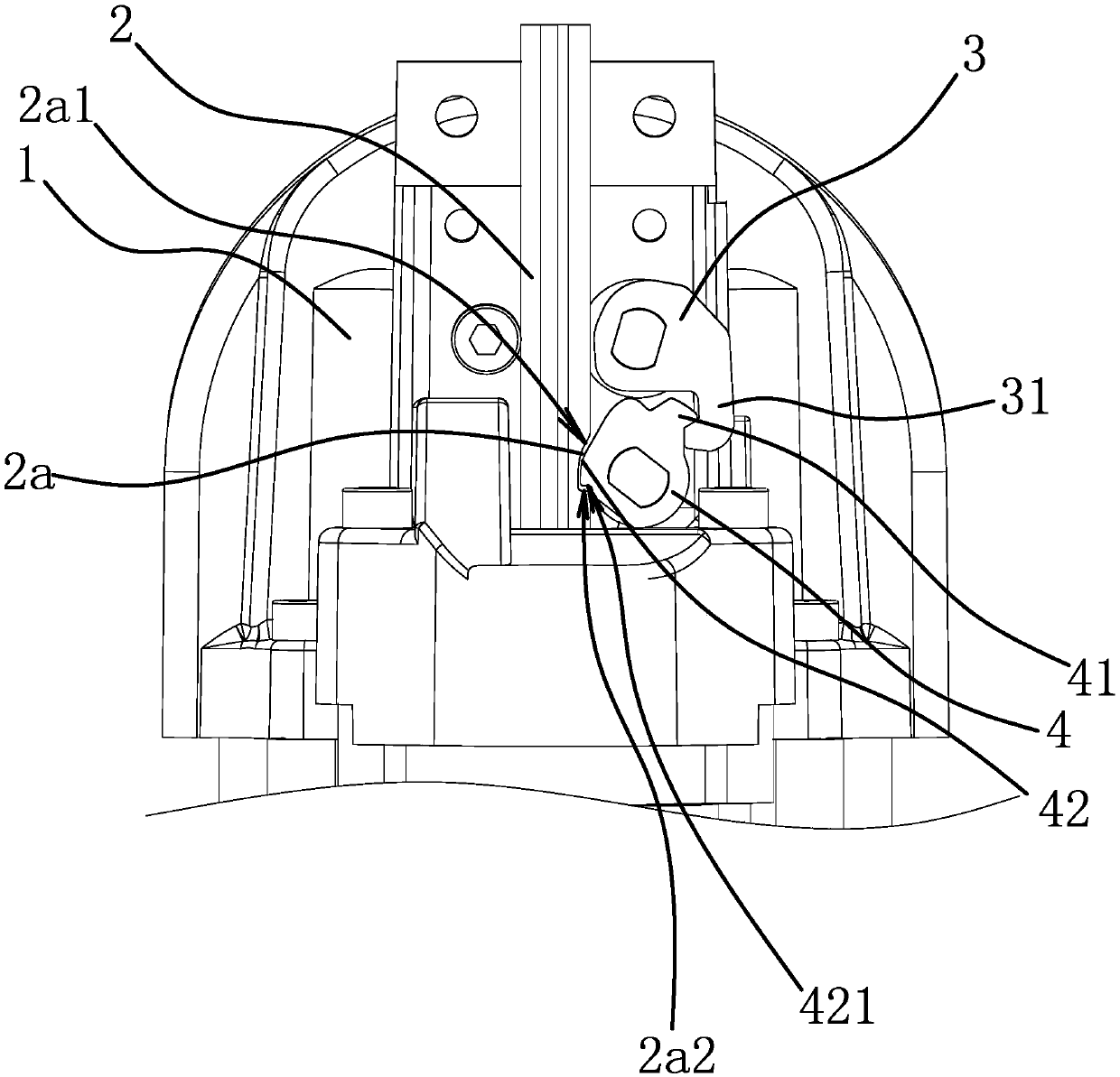
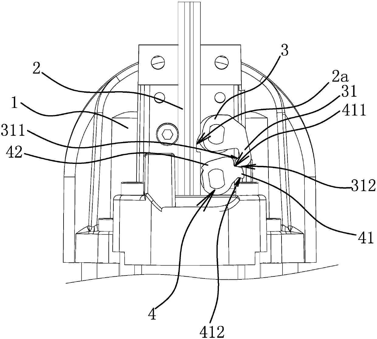
[0029] Specifically, as figure 1 As shown, the nailing gun includes a housing 1 and a striker 2 that can move back and forth relative to the housing 1 and has a groove 2a on one side, and a locking member 3 is rotatably connected to the housing 1, and the locking member 3 and the striker 2 An intermediate piece 4 is arranged between them, and the intermediate piece 4 is rotatably connected to the housing 1 . At the same time, the middle piece 4 has a locking part 1 41 and a locking part 2 42 respectively, and the middle piece 4 can rotate relative to the housing 1 so that the locking part 2 42 snaps into or escapes from the groove 2a. Such as figure 2 As shown, when the striker 2 is in the locked state, the intermediate piece 4 is engaged in the groove 2a of the striker 2 through the lock part 2 42 and has a movement tendency to rotate relative to the housing 1, and the lock part 3 can abut against the lock part 1 41 and prevent the middle piece 4 from rotating relative to ...

Embodiment 2

[0034] The technical solution in this embodiment is basically the same as the technical solution in Embodiment 1, the difference is that, as Figure 5 and Figure 6 As shown, in this embodiment, a chute 8 is provided on the housing 1, and the chute 8 is arranged obliquely relative to the advancing direction of the striker 2. The locking member 3 is located on one side of the chute 8 and is rotationally connected with the housing 1. Located on the other side of the chute 8. The middle piece 4 is slidably connected in the slide groove 8 , and the middle piece 4 can slide relative to the housing 1 so that the locking part 2 42 snaps into or escapes from the groove 2 a. The middle piece 4 is reset by the torsion spring 5, the torsion spring 5 is sleeved on the housing 1, the middle piece 4 has a boss 9, and the boss 9 has an annular groove, one end of the torsion spring 5 rests in the annular groove, and the other end against the housing 1. When the locking part 2 42 is stuck o...


PUM


Abstract

The invention provides a nailing gun, and belongs to the technical field of machinery. The problem how to improve the service life of a nailing gun is solved. The nailing gun comprises a shell and a striker capable of reciprocating relative to the shell, a locking piece and a middle piece capable of moving relative to the shell are arranged on the shell, the middle piece is located between the locking piece and the striker, and the middle piece is provided with a first locking part and a second locking part capable of clamping on the striker; and the locking piece can be propped against the first locking part and block the middle piece to move relative to the shell so that the second locking part keeps clamping connection with the striker, or the locking piece can unblock blocking so thatthe second locking part can move and release out of the striker. According to the nailing gun, by designing the middle piece between the locking piece and the striker, the position of the bonding locking point with the maximum friction force and easy to wear is transferred at the position between the middle piece and the locking piece and with the maximum locking design space so as to reduce the wear of the striker fundamentally, the locking failure of the striker is avoided, and the service life of the nailing gun is greatly improved accordingly.

Description

technical field [0001] The invention belongs to the technical field of machinery and relates to a nail gun. Background technique [0002] Nailer, also known as nail gun, has a wide range of applications in the decoration industry. According to different driving sources, it can be divided into electric nail guns, pneumatic nail guns, gas nail guns, manual nail guns, etc. Among them, the pneumatic nail gun uses the air pressure generated by the air pump as the power source, and the high-pressure gas drives the firing pin in the nail gun cylinder to perform a hammering movement, and the nails in the nail clip are nailed into the object or the nails are shot out. [0003] Specifically, the structure of a pneumatic nail gun includes a gun body, a cylinder, a balance valve, a switch assembly, a firing pin assembly, a locking mechanism for locking the firing pin, a cushion, a gun nozzle, a gun slot, and the like. For example, the structure of a nailing machine disclosed in Chines...

Claims


Application Information

Patent Timeline
Patent Type & Authority Applications(China)
IPC IPC(8): B25C1/04
CPCB25C1/047B25C1/06
Inventor 张华定
Owner TAIZHOU DINGBA POWER TOOLS
Why Eureka
Try Eureka