Pressing release pen

A pen holder and pen holder technology, applied in printing, writing utensils, writing parts, etc., can solve problems such as the complex structure of the pressing pen, achieve the effect of simple structure, low cost, and stability

Active Publication Date: 2019-04-12
温州市简系文具有限公司
View PDF6 Cites 2 Cited by
  • Summary
  • Abstract
  • Description
  • Claims
  • Application Information

AI Technical Summary

Problems solved by technology

[0006] The purpose of the present invention is to solve the problem of the complex structure of the existing pressing pen, and to provide a pressing and releasing pen, mainly through the mutual interaction between the elastic pressing fixing part arranged on the outside of the pen holder and the fixing groove arranged on the sleeve end. Cooperate to realize the pop-up of the refill; by pressing the elastic extrusion fixing piece to release the cooperation with the fixing groove, under the power provided by the elastic piece, the elastic extrusion fixing piece rebounds and cooperates with the bottom end of the sliding groove to realize the refill. take back

Method used


Image

  • Pressing release pen
  • Pressing release pen
  • Pressing release pen

Examples


Embodiment 1

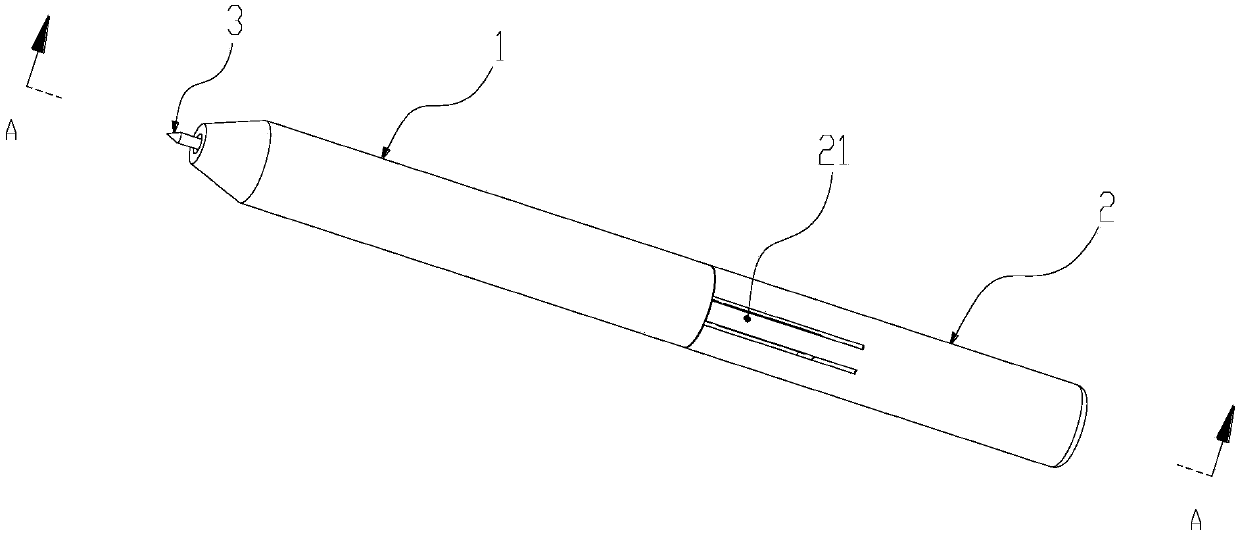
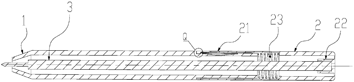
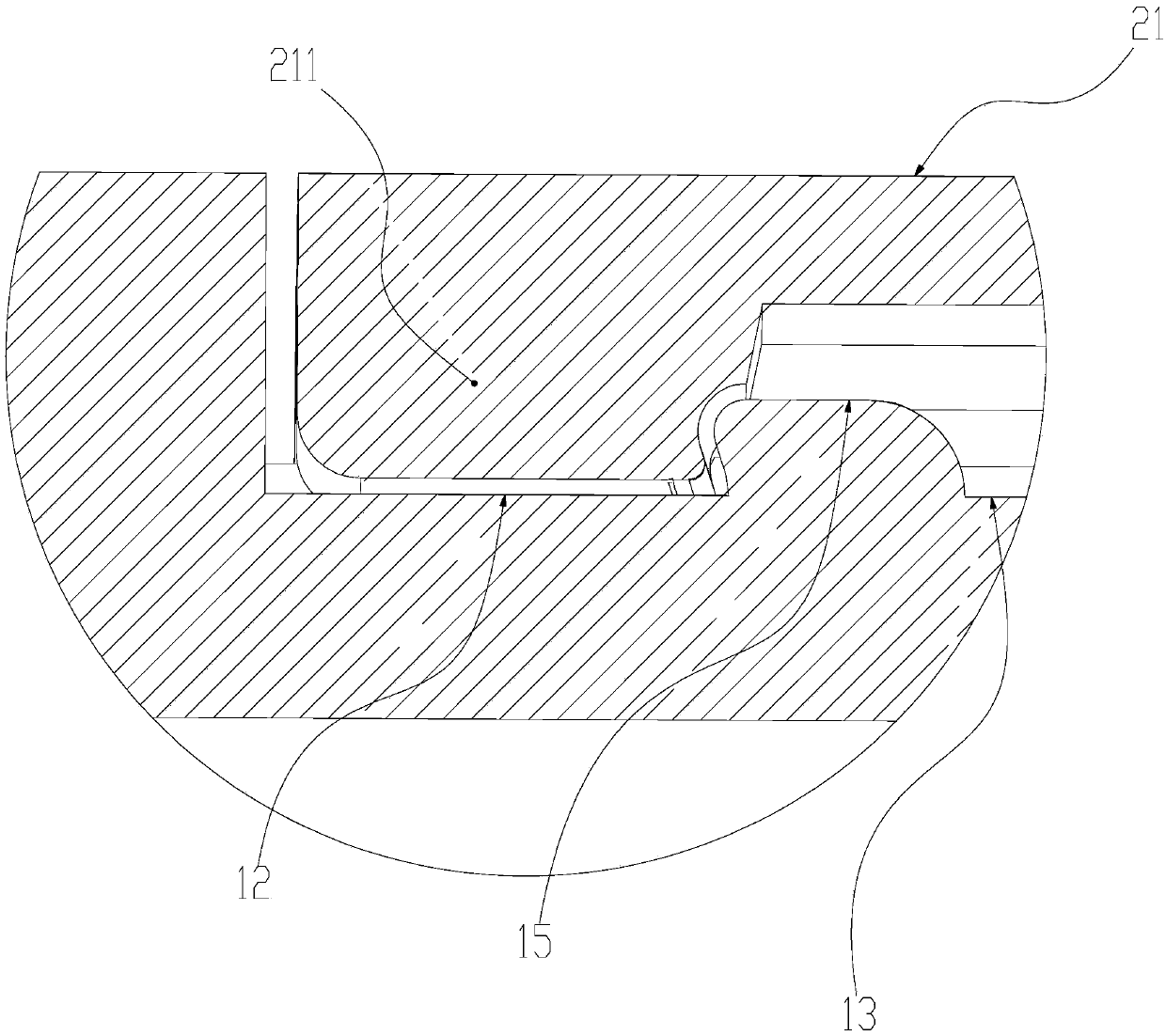
[0038] Such as Figures 1 to 4 A push-and-release pen shown includes a front pen holder 1, a rear pen holder 2, a pen core 3 and an elastic member. Wherein, the above-mentioned front pen holder 1 has a nib end and a sleeve end; as Figure 4 As shown, the socket end is an extension part whose outer diameter of the main body is smaller than that of the front penholder 1 body, and a fixing groove 12 and a sliding groove 13 are arranged on the circumferential outer wall of the socket end. The fixing groove 12 is arranged near the end of the nib, the inner end of the sliding groove 13 is connected to the fixing groove 12, and the outer end of the sliding groove 13 is a groove connected to the outer end surface of the sleeve end through a bending groove.

[0039]The above-mentioned rear pen container 2 has a pen core fixing groove 22 and a movable inner chamber 23, and the socket end of the front pen holder 1 and the movable inner chamber 22 of the rear pen holder 2 are socketed wi...

Embodiment 2

[0049] Such as Figures 5 to 7 A push-and-release pen shown includes a front pen holder 1, a rear pen holder 2, a pen core 3 and an elastic member.

[0050] The above-mentioned front penholder 1 has a nib end and a socket end, and a fixing groove 12 and a sliding groove 13 are arranged on the above-mentioned socket end. Rear pen container 2, described rear pen container 2 has pen core fixing groove 22 and movable inner cavity 23, the socket end of described front pen holder 1 and the movable inner cavity 22 of rear pen container 2 are mutually socketed, and described rear pen container 2 is provided with There is an elastic extrusion fixing part 21, and the elastic extrusion fixing part 21 is also provided with a matching protrusion 211, and the matching protrusion 211 is matched with the fixing groove 12, and the elastic extrusion fixing part 21 is extruded by an external force Afterwards, its structure will be deformed inward, causing the matching protrusion 211 to lift wit...


PUM


Abstract

The invention relates to a pen, in particular to a pressing release pen which comprises a front pen holder and a rear pen container. The front pen holder is provided with a pen head end and a sleevingend, the sleeving end is provided with a fixed groove and a sliding groove, the rear pen container is provided with a pen refill fixing groove and a movable inner cavity, the sleeving end of the front pen holder and the movable inner cavity of the rear pen container are in mutual sleeved connection, the rear pen container is provided with an elastic extrusion fixing part in the axial extension direction of the outer wall of the rear pen container, the outer end of the elastic extrusion fixing part is provided with a matching protrusion in the axial direction, and the matching protrusion is matched with the fixed groove. When the front pen holder and the rear pen container are in a first matched state, the writing end is retracted in the pen head end. When the front pen holder and the rearpen container are in a second matched state, the writing end is stretched out of the pen head end. By means of mutual matching between the elastic extrusion fixing part arranged on the outer side ofthe pen holder and the fixed groove arranged at the sleeving end, pen refill popup is achieved. The elastic extrusion fixing part is pressed to release matching with the fixed groove, pen refill retraction is achieved.

Description

technical field [0001] The invention relates to a pen, in particular to a press-and-release pen. Background technique [0002] Most of the pressing pens generally used in the market are to realize the pop-up and retraction of the pen core by pressing the pressing head at the tail of the pen holder. [0003] The main principle of the general press pen is realized by the sliding claw cover, the push rod and the guide rail inside the pen barrel. The push rod pushes the sliding claw cover to move to the tip position at the bottom of the guide rail. Under the push of the spring at the tip of the pen, the sliding claw cover moves to the right Turn sideways, and the push rod will rebound upward under the action of the spring. After passing the critical point, the sliding claw will continue to rotate to the right, and will be stuck at the guide rail. At this time, the pen core will pop out, and the push rod will continue to rebound Go to the top, repeat the previous step, and the r...

Claims


Application Information

Patent Timeline
IPC IPC(8): B43K24/03
CPCB43K24/03
Inventor 余成鹏
Owner 温州市简系文具有限公司
Why Eureka
Try Eureka