Check patentability & draft patents in minutes with Patsnap Eureka AI!

Support arrangement for an evaporator source

一种承载器、蒸发器的技术,应用在真空蒸发镀覆、离子注入镀覆、涂层等方向,能够解决损害出流行为等问题

Inactive Publication Date: 2019-04-12
NICE SOLAR LLC +1
View PDF7 Cites 0 Cited by
  • Summary
  • Abstract
  • Description
  • Claims
  • Application Information

AI Technical Summary

Problems solved by technology

[0004] In this case, it must be ensured that the outflow path extending from the crucible to the individual outflow nozzles is sufficiently heated so that the vapors emerging from the crucible do not condense on the inner walls of the crucible housing or the housing of the vapor distributor, which could damage the outlet flow. for

Method used


Image

  • Support arrangement for an evaporator source
  • Support arrangement for an evaporator source
  • Support arrangement for an evaporator source

Examples


Embodiment Construction

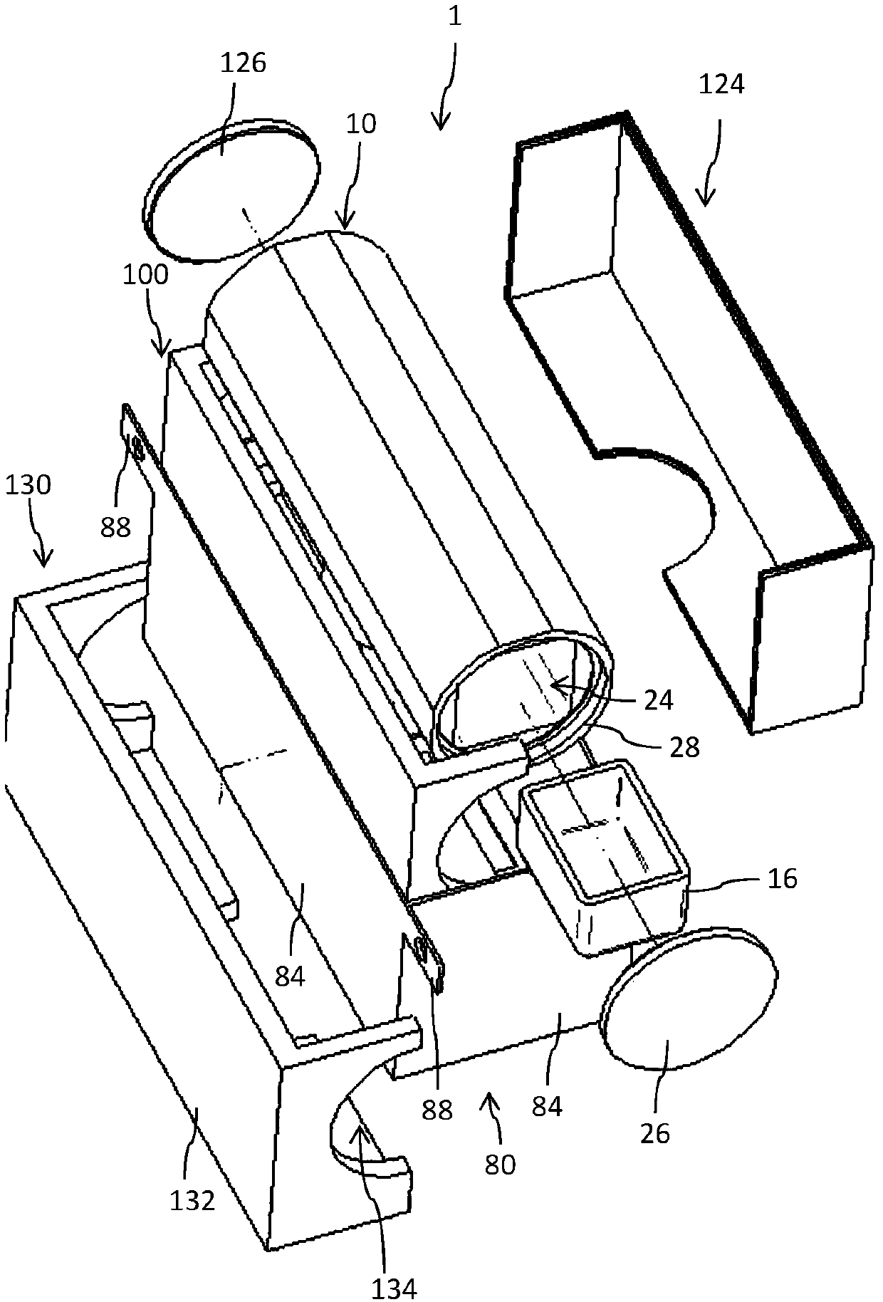
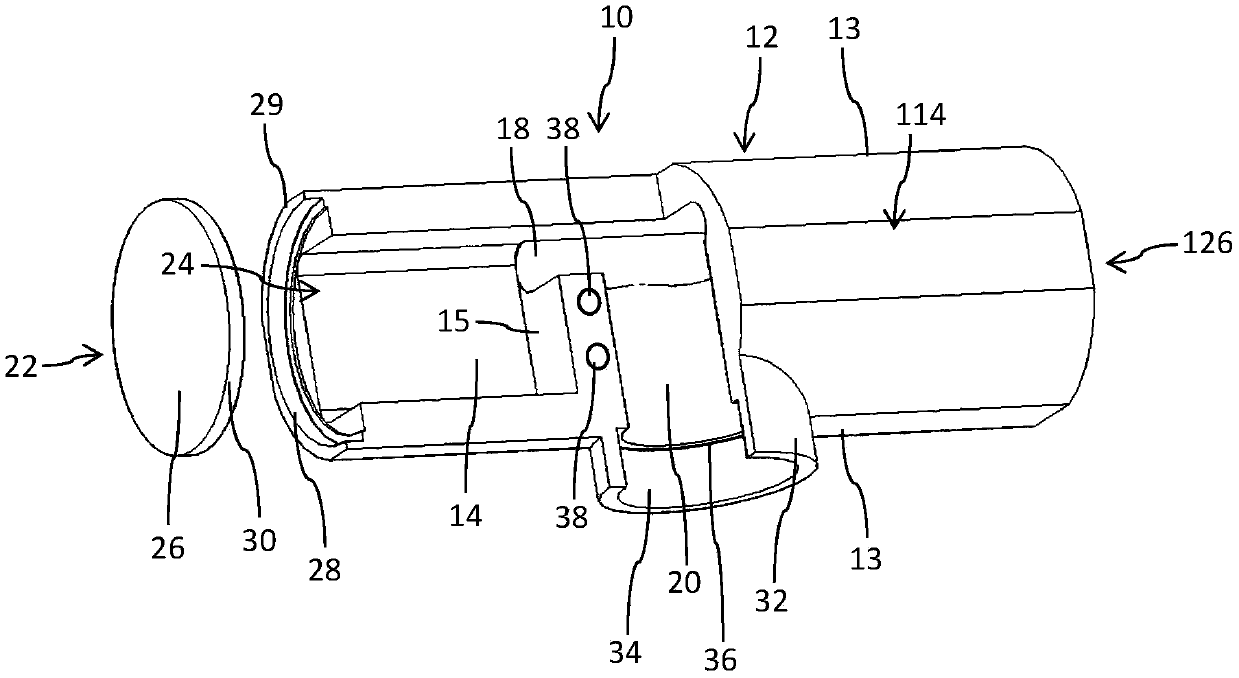
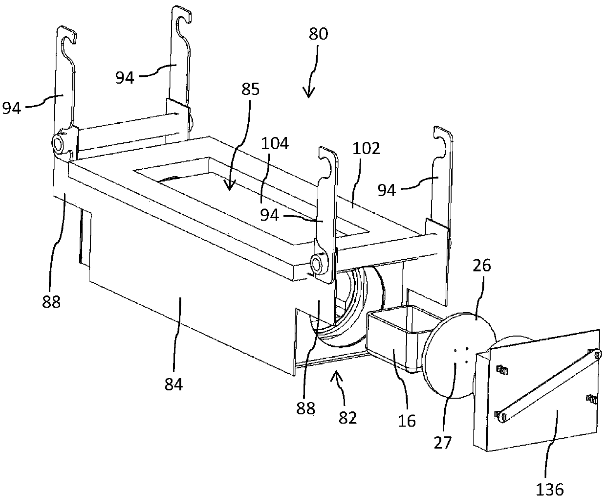
[0065] exist figure 1 , 4 An evaporator arrangement with an evaporator source 10 is shown in and 5 . figure 2 The evaporator source 10 shown in isolation in , has a single-piece housing 12 made of graphite. The housing 12, which currently has a nearly cylindrical configuration, has a first vapor chamber 14 and a second vapor chamber 114, the latter in Figure 8 are only shown in cross-section. exist figure 2 The vapor chamber 14 shown in is used to receive e.g. figure 1 , 3 , 4 and 5, the evaporant container 16 is generally designed as an evaporator crucible.

[0066] The evaporant container 16 can also be made monolithically from graphite. The evaporator source 10 or its single-piece graphite housing 12 has, in addition to the two vapor chambers 14 , 114 , a vapor-conducting channel 20 arranged, for example centrally, between these vapor chambers 14 , 114 . The substantially cylindrical channel 20 , which defines an axial direction, extends approximately perpendicul...


PUM


Abstract

The invention relates to a self-supporting support arrangement for an evaporator source (10) for treating the surface of at least one substrate, said support arrangement comprising a bottom (82) and asidewall structure (84) which is joined to the bottom (82). The bottom (82) and the sidewall structure (84), which are made of a graphite fiber material, form a receiving device (85) into which the evaporator source (10) can be inserted. The invention further relates to an evaporator arrangement comprising a support arrangement of said type and comprising an evaporator source (10) disposed in thesupport arrangement.

Description

[0001] This application is a divisional application of an invention patent application with an application date of May 20, 2015, an application number of 201580026919.0, and a title of "carrier device for evaporator source". technical field [0002] The invention relates to a carrier arrangement for an evaporator source for the surface treatment of at least one substrate. The evaporator source is designed in particular for evaporating metals, such as copper, and is designed for the surface coating process of one or more substrates. Furthermore, the invention relates to an evaporator arrangement having a carrier arrangement and an evaporator source arranged in the carrier arrangement. Background technique [0003] Thermal evaporation sources for supplying vaporous materials, for example during surface coating or surface treatment processes, are known in various designs from the prior art. Thus, US 2010 / 0285218 A1 shows, for example, an evaporator having a housing receiving a...

Claims


Application Information

Patent Timeline
Patent Type & Authority Applications(China)
IPC IPC(8): C23C14/14C23C14/24
CPCC23C14/14C23C14/243
Inventor G·乌尔温登E·格罗斯U·恩勒特A·索格A·斯特劳布P·冯比斯马克M·皮施L·科诺斯A·马里恩菲尔德
Owner NICE SOLAR LLC
Features
  • R&D
  • Intellectual Property
  • Life Sciences
  • Materials
  • Tech Scout
  • Unparalleled Data Quality
  • Higher Quality Content
  • 60% Fewer Hallucinations
Learn More