
Patient call device for night use

A technology for calling devices and wards, which is applied in the direction of visible signal devices, signal devices, instruments, etc., and can solve the problems of easily affecting the rest of other patients, patients who cannot be accurately found, and patients who cannot call in time

Inactive Publication Date: 2020-09-29
THE FIRST AFFILIATED HOSPITAL OF ARMY MEDICAL UNIV
View PDF12 Cites 0 Cited by
  • Summary
  • Abstract
  • Description
  • Claims
  • Application Information

AI Technical Summary

Problems solved by technology

[0003] Due to the limited basic medical resources of the hospital, in the same ward, there are generally multiple patients and their accompanying family members. When the patient needs to call the medical staff or doctor at night, it is usually necessary to turn on the indicator light in the ward to find the corresponding patient. call device, which is very easy to affect the rest of other patients, which is not conducive to the recovery of the patient's condition; at the same time, the indicator light is generally set at the entrance of the ward, and the patient must first turn on the indicator light and then press the button or button of the call device. bed, the patient cannot accurately find the button of the call device, resulting in the patient not being able to call the nurse or doctor in time, and it is easy to cause delays in the treatment of the patient

Method used


Image

  • Patient call device for night use
  • Patient call device for night use
  • Patient call device for night use

Examples


Embodiment Construction

[0024] The following will be further described in detail through specific embodiments.

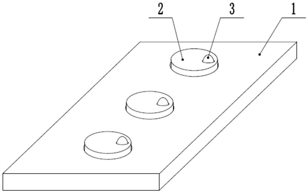
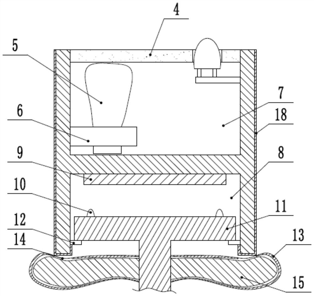
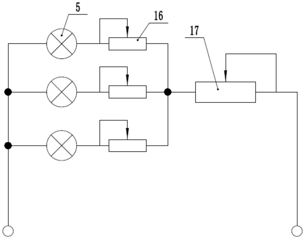
[0025] The reference signs in the drawings of the specification include: housing 1, call button 2, temperature sensing module 3, transparent plate 4, indicator light 5, lamp holder 6, cavity 7, card slot 8, conductive sheet 9, contacts Switch 10, key base 11, block 12, elastic air bag 13, insertion hole 14, sponge 15, first adjustable resistor 16, second adjustable resistor 17, water-absorbing layer 18.

[0026] The embodiment is basically as attached figure 1 , figure 2 , image 3 with Figure 4 As shown: it includes a call terminal located beside the hospital bed. The call terminal includes a housing 1 and a circuit board clamped inside the housing 1. A plurality of call buttons 2 that can be automatically reset after being pressed are installed on the circuit board. The call button 2 After being pressed, a call signal is sent. In this embodiment, three call buttons 2 are taken as a...


PUM


Abstract

The invention relates to the field of hospital ward call equipment, in particular to a hospital ward calling device convenient to use at night. The hospital ward calling device comprises a calling terminal, the calling terminal comprises a shell and a circuit board in the shell, the circuit board is provided with a plurality of calling buttons capable of automatically resetting, through holes internally provided with transparent plates are formed in the top end faces of the calling buttons, light-proof identifiers are fixedly arranged in the transparent plates, cavities are formed in the calling buttons correspondingly, and the cavities are internally provided with indicating lamp indicating branch circuits which are mutually connected in parallel correspondingly; the circuit board is provided with a photosensitive module with a light brightness value and a resistance value which are in negative correlation, the photosensitive module is electrically connected with a control module, thephotosensitive module detects the light brightness value and sends the light brightness value to the control module, the control module is in control connection with a dimming module located in an indicating lamp power supply circuit, the dimming module is in series connection with the indicating branch circuits, and the control module controls the dimming module to lower the light brightness ofindicating lamps when the light brightness value is smaller than a bright threshold. The hospital ward calling device automatically adjusts the brightness of the indicating lamps at night, and rest ofpatients is not affected.

Description

technical field [0001] The invention relates to the field of ward calling equipment, in particular to a ward calling device which is convenient for use at night. Background technique [0002] With the development of science and technology, the level of technology of ward-related facilities is also improving. A call device is installed in the ward for patients to remotely call the nurse or doctor on duty. The call device can directly and quickly transmit the request of the inpatient to the nurse or doctor on duty. The call device has become an important device to strengthen communication between doctors and patients. [0003] Due to the limited basic medical resources of the hospital, in the same ward, there are generally multiple patients and their accompanying family members. When the patient needs to call the medical staff or doctor at night, it is usually necessary to turn on the indicator light in the ward to find the corresponding patient. call device, which is very ea...

Claims


Application Information

Patent Timeline
Patent Type & Authority Patents(China)
IPC IPC(8): G08B5/36G08B25/01H05B45/12H05B45/18
CPCG08B5/36G08B25/016H05B47/10
Inventor 夏曼霖
Owner THE FIRST AFFILIATED HOSPITAL OF ARMY MEDICAL UNIV
Learn More