Projection cloth with touch function and imaging touch system of projection cloth

A technology of touch function and projection cloth, which is applied in the input/output process of data processing, optics, instruments, etc., can solve the problems of sharing inconvenience, and achieve the effect of low unit cost, convenient transportation and shipment, and simple production process

Inactive Publication Date: 2012-08-22
UC NANO TECH CO LTD
View PDF5 Cites 10 Cited by
  • Summary
  • Abstract
  • Description
  • Claims
  • Application Information

AI Technical Summary

Problems solved by technology

However, whether it is forward or rear projection, it can only be used for the user to project the image on the projection cloth to realize the imaging function. Any modification or key explanation of the imaging cont

Method used


Image

  • Projection cloth with touch function and imaging touch system of projection cloth
  • Projection cloth with touch function and imaging touch system of projection cloth
  • Projection cloth with touch function and imaging touch system of projection cloth

Examples


Embodiment 1

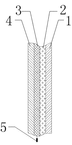
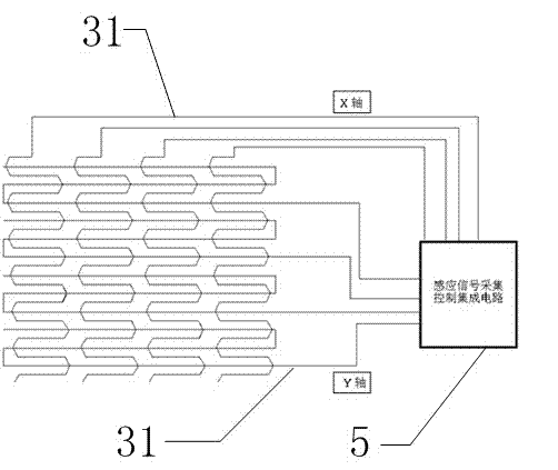
[0027] A projection cloth with touch function in this embodiment, such as figure 1 and figure 2 As shown, it includes a substrate 1, the front of the substrate 1 is a touch operation surface, and the back of the substrate 1 is sequentially coated with an imaging layer 2 and a wire layer 3 for sensing touch signals; the area of ​​the wire layer 3 is smaller than or It is equal to the imaging area of ​​the imaging layer 2, and the area of ​​the imaging layer 2 is smaller than or equal to the area of ​​the substrate 1. A protection layer 4 is also provided on the wire layer 3 . The imaging layer 2 is a front projection imaging layer or a rear projection imaging layer; the conductor layer 3 is a warp and weft network interlaced by ultra-fine conductors 31 wound along the X-axis and Y-axis directions respectively, and the ultra-fine conductors 31 are at the intersection point are insulated from each other, and the space surrounded by each grid forms an induction unit. The induct...

Embodiment 2

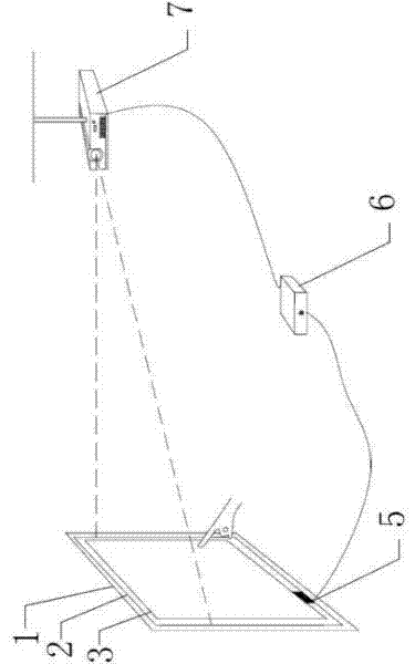
[0030] This embodiment is based on the touch imaging system of the projection cloth of Embodiment 1, such as image 3 As shown, the induction signal acquisition control integrated circuit 5 of the projection cloth is connected to the calculation control unit 6 through an interface, and the calculation control unit 6 is connected to the projection imaging device 7 through wired communication. The imaging layer 2 is an orthographic projection imaging layer made of diffuse reflection material, and the corresponding projection imaging device 7 is an orthographic projection imaging, and its projection direction is facing the front of the substrate 1 . The interface is set on the computing control unit 6, and the interface is a wired serial or parallel interface, including a USB interface and / or an RS-232 interface. Wired communication methods include serial port, USB or parallel port.

[0031] Optionally, the computing control unit 7 is connected to a remote switch device (not sho...

Embodiment 3

[0039] This embodiment is based on the touch imaging system of the projection cloth of Embodiment 1, which has roughly the same structure as that of Embodiment 2 above, as Figure 4 As shown, the induction signal acquisition control integrated circuit 5 of the projection cloth is connected to the calculation control unit 6 through an interface, and the calculation control unit 6 is connected to the projection imaging device 7 through wireless communication. The imaging layer 2 is a rear projection imaging layer made of transmissive material, and the corresponding projection imaging device 7 is rear projection imaging, and its projection direction is facing the back of the substrate 1 . The interface is set on the computing control unit 6, and the interface is a wireless interface, including a cellular interface, a WiFi interface and / or a BlueTooth interface. Wireless communication methods include BlueTooth, infrared or radio frequency.


PUM


Abstract

The invention discloses a piece of projection cloth with a touch function. The projection cloth comprises a base material, wherein the front surface of the base material is a touch operation surface; an imaging layer and a conducting wire layer which is used for sensing a touch signal are pasted and covered on the back surface of the base material in sequence; the imaging layer is an orthographic projection imaging layer or a back projection imaging layer; the conducting wire layer is a warp and weft net which is formed by winding and crosswise interlacing ultra-fine conducting wires along an X axis direction and a Y axis direction respectively, and the ultra-fine conducting wires are insulted with one another at the cross points; a space defined by each grid forms a sensing unit; and the output end of the conducting wire layer is connected with an induced signal acquisition control integrated circuit. The imaging touch system has an effect of projection imaging and the touch function, can effectively perform human-computer interaction while displaying information, and realizes real-time, convenience and high-efficiency of meetings, school-teaching and lectures.

Description

technical field [0001] The invention belongs to the field of touch technology, and in particular relates to a projection cloth capable of realizing projection imaging and touch function and an imaging touch system thereof. Background technique [0002] During meetings, lectures, and lectures, projectors are usually used to project information such as text, pictures, and videos onto the projection cloth to share relevant information with everyone. The general projection methods are divided into front projection and rear projection. However, whether it is forward or rear projection, it can only be used for the user to project the image on the projection cloth to realize the imaging function. Any modification or key explanation of the imaging content needs to be carried out by the user on another computing control unit. Manual changes, or explanations on other substrates, or pre-edited perfection, this brings a lot of inconvenience to the sharing of information. Contents of ...

Claims


Application Information

Patent Timeline
IPC IPC(8): G06F3/041G03B21/60
Inventor 刘泽江翟立娜王传刚
Owner UC NANO TECH CO LTD
Why Eureka
Try Eureka