
Mobile phone charging device and mobile phone protection shell

A mobile phone charging and mobile phone technology, which is applied in the direction of circuit devices, battery circuit devices, collectors, etc., can solve the problems of short battery life of smart phones, the inability to realize free switching of external charging circuits and internal charging circuits, and reduce satisfaction, etc.

Active Publication Date: 2019-04-12
重庆大唛物联网科技有限公司
View PDF5 Cites 0 Cited by
  • Summary
  • Abstract
  • Description
  • Claims
  • Application Information

AI Technical Summary

Problems solved by technology

[0002] At present, with the progress and development of science and technology, the current smart phones have been widely promoted, and almost everyone has a smart phone in their hands. In the use of smart phones, their intelligence has brought great convenience to people. , but the current smartphones have a great disadvantage, that is, the battery life of the smartphone is short and needs to be charged repeatedly, that is, it needs to be charged at least once a day, so as to meet the user's requirements, and for some smartphones As far as mobile phones are concerned, the battery life is even shorter, and even needs to be charged more than twice a day.
[0003] In the traditional technology, the usual mobile phone case basically does not have the charging function. Even if it has the charging function, it cannot realize the free switching between the external charging circuit and the internal charging circuit when charging the mobile phone, which greatly reduces the satisfaction of users. Spend

Method used


Image

  • Mobile phone charging device and mobile phone protection shell
  • Mobile phone charging device and mobile phone protection shell
  • Mobile phone charging device and mobile phone protection shell

Examples


Embodiment Construction

[0030] In order to make the purpose, technical solution and advantages of the present application clearer, the present application will be further described in detail below in conjunction with the accompanying drawings and embodiments. It should be understood that the specific embodiments described here are only used to explain the present application, and are not intended to limit the present application.

[0031] It can be understood that the terms "first", "second" and the like used in this application may be used to describe various elements herein, but these elements are not limited by these terms. These terms are only used to distinguish one element from another element. For example, a first POMS tube could be termed a second POMS tube, and, similarly, a second POMS tube could be termed a first POMS tube, without departing from the scope of the present application. Both the first POMS tube and the second POMS tube are POMS tubes, but they are not the same POMS tube.

...


PUM


Abstract

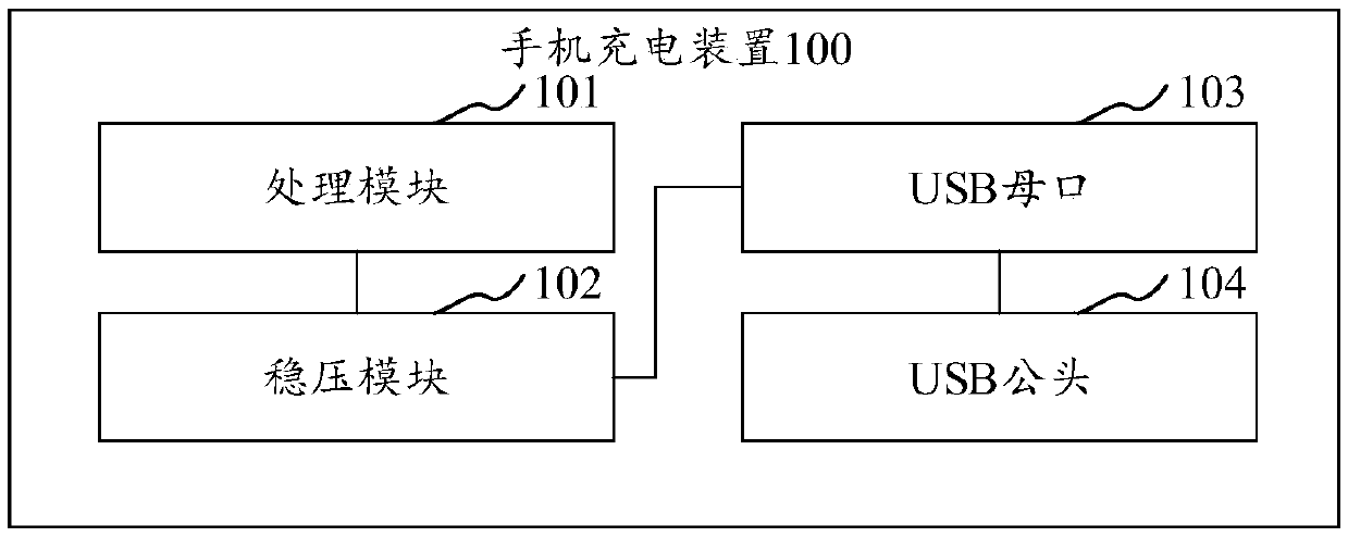
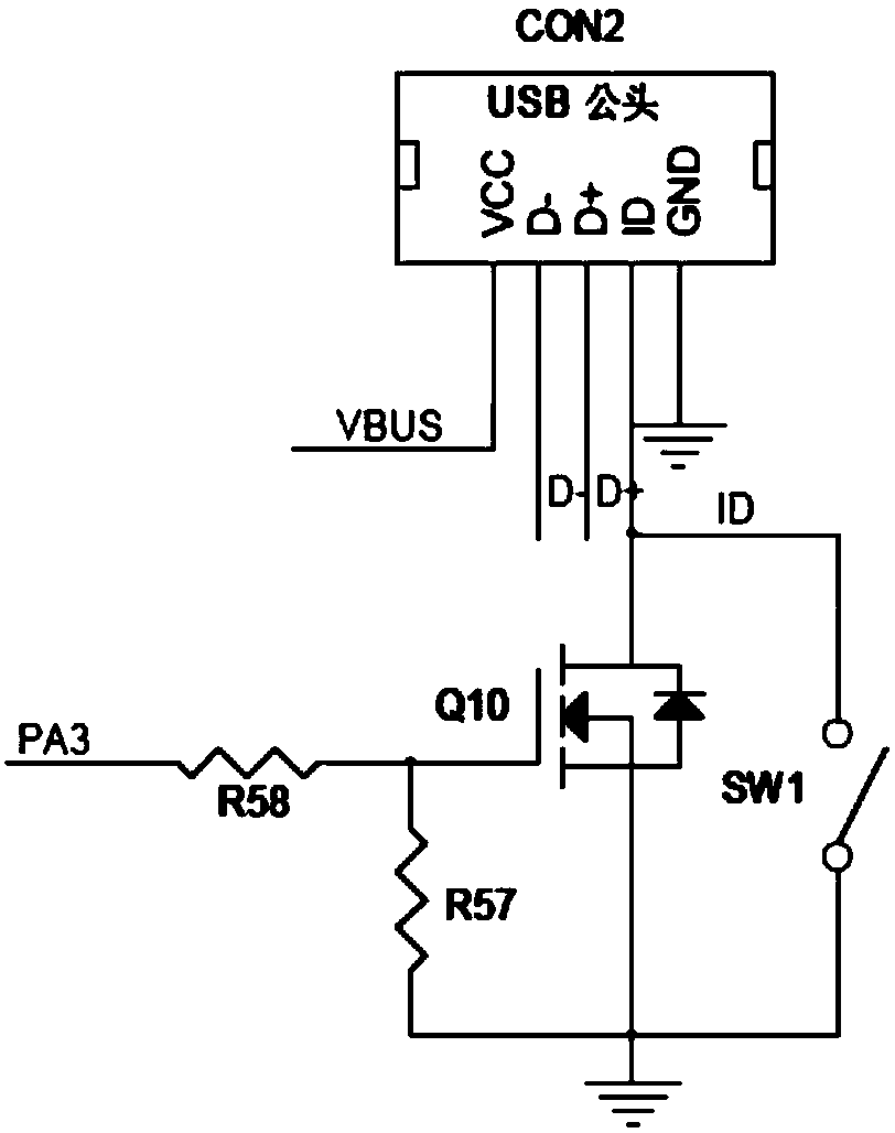
The invention relates to a mobile phone charging device and a mobile phone protection shell. The mobile phone charging device comprises a processing module, a voltage stabilization module, a USB female port and a USB male head, wherein the processing module is electrically connected with a touch panel; the voltage stabilization module is electrically connected with the processing module and is used for supplying power for the processing module; the USB female port is electrically connected with the processing module and is used for being connected with an adapter; and the USB male head is usedfor being connected with a mobile phone, and the USB male head is electrically connected with the processing module so as to realize USB communication between the processing module and the mobile phone and to charge the mobile phone. According to the mobile phone charging device, the free switching function of a charging circuit is realized, and external circuit charging cannot be influenced, andthe external charging circuit can be switched by enabling the USB female head to be inserted into the external adapter, so that the operation of a user is facilitated, and the use satisfaction degreeof the user is improved.

Description

technical field [0001] The invention relates to the technical field of circuit design, in particular to a mobile phone charging device and a mobile phone protective case. Background technique [0002] At present, with the progress and development of science and technology, the current smart phones have been widely promoted, and almost everyone has a smart phone in their hands. In the use of smart phones, their intelligence has brought great convenience to people. , but the current smartphones have a great disadvantage, that is, the battery life of the smartphone is short and needs to be charged repeatedly, that is, it needs to be charged at least once a day, so as to meet the user's requirements, and for some smartphones As far as mobile phones are concerned, the battery life is relatively short, and even more than two charging times are required in one day. [0003] In the traditional technology, the usual mobile phone case basically does not have the charging function. Ev...

Claims


Application Information

Patent Timeline
IPC IPC(8): H02J7/00
CPCH02J7/0071H02J7/00
Inventor 叶永禄
Owner 重庆大唛物联网科技有限公司
Learn More