Intelligent air pressure knee joint convenient to wear

A knee joint, air pressure technology, applied in medical science, artificial legs, prostheses, etc., can solve problems such as poor contact, infiltration, and easily damaged batteries, and achieve the effect of improving sealing

Inactive Publication Date: 2021-09-17
金华德仁康复辅具有限公司
View PDF0 Cites 0 Cited by
  • Summary
  • Abstract
  • Description
  • Claims
  • Application Information

AI Technical Summary

Problems solved by technology

[0002] The intelligent air pressure knee joint is a combined four-axis air pressure knee joint that can automatically adjust the joint swing rhythm. Its main feature is that the joint can automatically adjust according to the user's pace and gait through its own intelligent control system. Joint motion damping is used to change the joint swing speed to better meet the user's pace and gait, so that the user can obtain a more natural and good gait. The intelligent pneumatic knee joint is often used on the prosthesis to make the prosthesis more flexible , some of the current smart pneumatic knee joints are installed on the prosthesis by screws, so that it is convenient to install and wear the smart pneumatic knee joint on the prosthesis, but there are some problems in the use of some of the current smart pneumatic knee joints, and some of the current smart pneumatic knee joints The joint needs to be charged with a charging cable when it is in use, but there is no dust-proof protection structure at the charging port of some smart air pressure knee joints. When not charging, the inside of the charging port is easy to accumulate dust, which is likely to cause poor contact and affect charging. At the same time, the battery cylinder and the cylinder cover of some smart pneumatic knee joints do not have a sealing mechanism. When used in rainy days, rainwater is likely to seep into the interior of the battery cylinder from the contact between the battery cylinder and the cylinder cover, which is easy to damage the battery.

Method used


Image

  • Intelligent air pressure knee joint convenient to wear
  • Intelligent air pressure knee joint convenient to wear
  • Intelligent air pressure knee joint convenient to wear

Examples


Embodiment Construction

[0019] The following will clearly and completely describe the technical solutions in the embodiments of the present invention with reference to the accompanying drawings in the embodiments of the present invention. Obviously, the described embodiments are only some, not all, embodiments of the present invention. Based on the embodiments of the present invention, all other embodiments obtained by persons of ordinary skill in the art without making creative efforts belong to the protection scope of the present invention.

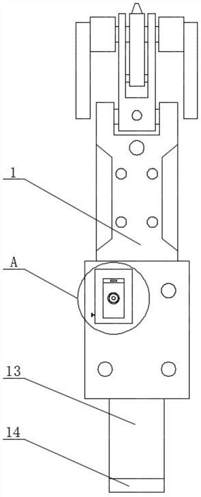
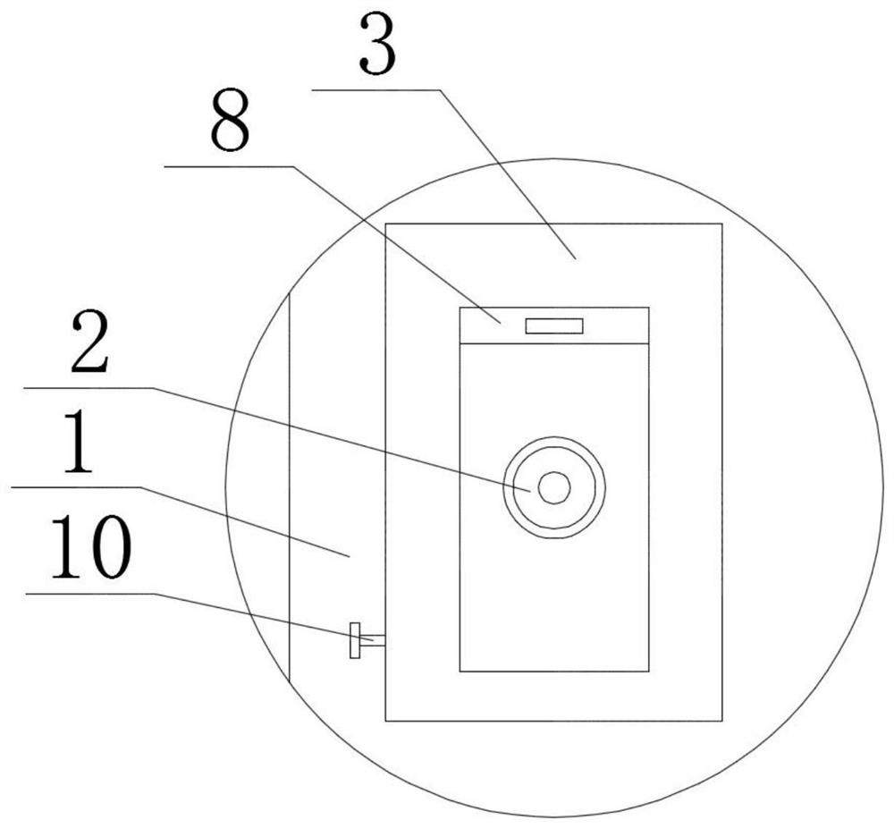
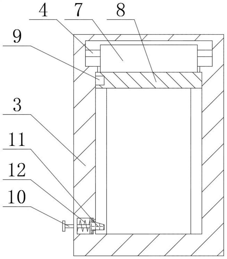
[0020] see Figure 1-5 , the present invention provides a technical solution:

[0021] An easy-to-wear intelligent air pressure knee joint, comprising a knee joint body 1, a charging port 2, a dust-proof frame 3 and a battery cartridge 13, the charging port 2 is opened at the bottom of the front face of the knee joint body 1, the dust-proof frame 3 and the knee joint body 1 is fixedly connected, the battery cylinder 13 is fixedly connected with the knee joint...


PUM


Abstract

The invention relates to the field of intelligent air pressure knee joints, and particularly relates to an intelligent air pressure knee joint convenient to wear. The intelligent air pressure knee joint comprises a knee joint body, a charging port, a dustproof frame and a battery cylinder, wherein the charging port is formed in the bottom of the front end surface of the knee joint body, the dustproof frame is fixedly connected with the knee joint body, the battery cylinder is fixedly connected with the knee joint body, the bottom end surface of the battery cylinder is in threaded connection with a cylinder cover, and the inner side of the battery cylinder is fixedly connected with a sleeve rod. According to the intelligent air pressure knee joint, the dustproof frame, shielding cloth and a push plate are arranged, when the knee joint body is not charged, the shielding cloth is pulled out of the dustproof frame by pulling the push plate, the shielding cloth and the push plate are pulled to the bottom of the dustproof frame, so that the charging port in the knee joint body can be subjected to dustproof protection when the knee joint body is not charged, dust and sundries cannot be accumulated in the charging port, the situation of poor contact cannot occur, and charging is not influenced.

Description

technical field [0001] The invention relates to the field of intelligent air pressure knee joints, in particular to an intelligent air pressure knee joint which is easy to wear. Background technique [0002] The intelligent air pressure knee joint is a combined four-axis air pressure knee joint that can automatically adjust the joint swing rhythm. Its main feature is that the joint can automatically adjust according to the user's pace and gait through its own intelligent control system. The movement damping of the joints is used to change the swing speed of the joints so that it better conforms to the user's pace and gait, so that the user can obtain a more natural and good gait. The intelligent air pressure knee joint is often used on the prosthesis to make the prosthesis more flexible , some of the current smart pneumatic knee joints are installed on the prosthesis by screws, so that it is convenient to install and wear the smart pneumatic knee joint on the prosthesis, but...

Claims


Application Information

Patent Timeline
Patent Type & Authority Applications(China)
IPC IPC(8): A61F2/64A61F2/70
CPCA61F2/64A61F2/68
Inventor 蒋罗辉
Owner 金华德仁康复辅具有限公司
Why Eureka
Try Eureka