High-efficiency lubricating oil stirring device

A stirring device and lubricating oil technology, which is applied to mixers with rotating stirring devices, mixer accessories, transportation and packaging, etc., can solve the problems of affecting product quality, low mixing efficiency, poor uniform effect, etc., and achieve ingenious structural design, Wide range of stirring, fine stirring effect

Inactive Publication Date: 2017-11-17
WUHU YIZE SMALL & MEDIUM ENTERPRISE PUBLIC SERVICE CO LTD
View PDF2 Cites 5 Cited by
  • Summary
  • Abstract
  • Description
  • Claims
  • Application Information

AI Technical Summary

Problems solved by technology

After adding the additive to the base oil of the lubricating oil, it is necessary to stir the base oil and the additive so that the two are evenly mixed, so that the performance is better and more stable during work. However, the lubricating oil stirring equipment in the prior art, Most of them have simple structure, low stirring efficiency, poor uniform effect, and affect product quality
[0004] For example, the utility model patent with the Chinese Publication No. CN 205199390U discloses a tank body, the top of the tank body is provided with a feed port, the bottom of the tank body is provided with a discharge port, and the bottom of the tank body is provided with legs. The upper part of the body is provided with a motor, which is connected to a shaft, and a paddle for stirring lubricating oil is provided on the shaft, and the paddle provided on the shaft includes paddle A and paddle B, and the paddle A is set at the middle end of the shaft, the paddle B is set at the lower end of the shaft, the paddle A is paddle type, and the paddle B is downward anchor type; a jacket is arranged outside the tank, so The jacket is provided with a jacket inlet and a jacket outlet; the tank is provided with a manhole; the motor and the shaft are connected by a coupling; in this design, the paddles on the shaft include paddle-type paddles And anchor paddles, only stirring at a certain position, the stirring efficiency is low
[0005] Another example is that the utility model patent with the Chinese Publication No. CN 205095698U discloses a high-efficiency mixing tank, including a base, two opposite supports vertically fixed on the base, and a mixing tank arranged between the two supports. The tank body is provided with the stirring device and the defoaming device in the tank body of the stirring tank, and the filling cover arranged on the top of the tank body of the stirring tank, and the outer wall of the tank body of the stirring tank is provided with two The support shaft extending outward in the diameter direction of the body, the support shaft is rotatably connected with the bracket, and the top side of the stirring tank body is provided with a discharge nozzle. This design is only carried out by the stirring blades on the stirring shaft. Stirring, low stirring efficiency, poor uniformity

Method used


Image

  • High-efficiency lubricating oil stirring device
  • High-efficiency lubricating oil stirring device
  • High-efficiency lubricating oil stirring device

Examples


specific Embodiment approach

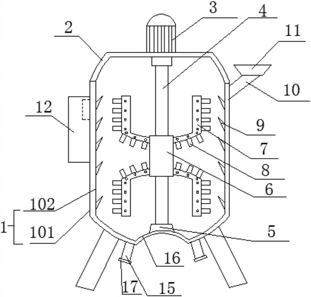
[0021] figure 1 Show the specific embodiment of the present invention: a kind of high-efficiency stirring device for lubricating oil, comprising stirring tank 1, the upper end of described stirring tank 1 is provided with feed port 11, and the lower end is provided with discharge port 15, and described discharge port 15 is provided with There is a sealing cover 17, the upper end of the stirring tank 1 is provided with a cover 2, the cover 2 is provided with a motor 3, the bottom of the stirring tank 1 is provided with a fixing seat 5, and the output shaft of the motor 3 is connected to There is a lead screw 4, the lower end of the lead screw 4 is rotatably connected with the fixed seat 5, the lead screw 4 is provided with a slide seat 6 threaded with the lead screw 4, and the two ends of the slide seat 6 are provided with symmetrical Stirring frame 7, described stirring frame 7 is provided with some scrapers 8 along the side wall of stirring frame 7, and the inner wall of desc...

Embodiment 2

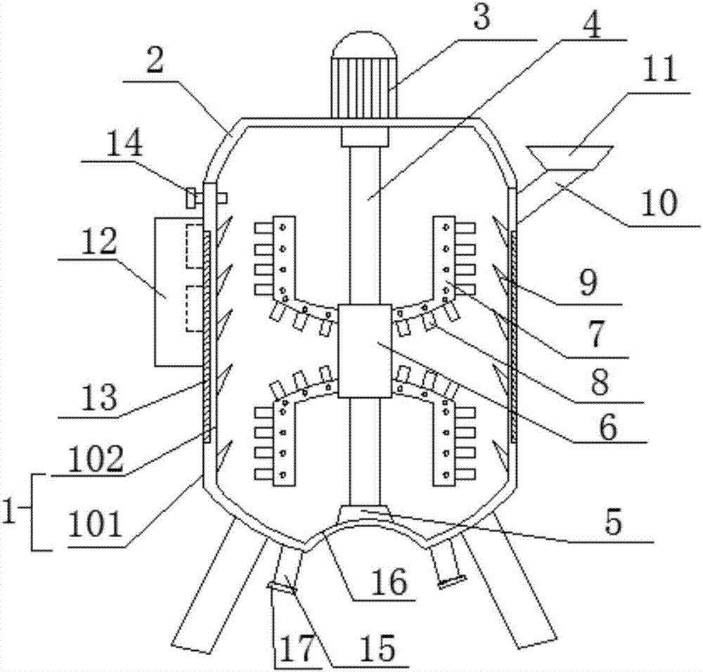
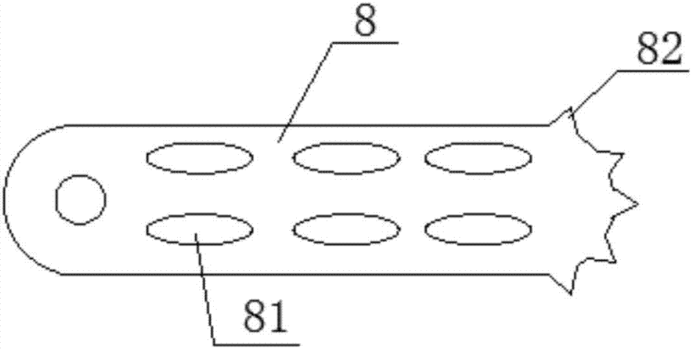
[0025] figure 2 with image 3 Show the specific embodiment of the present invention: a kind of high-efficiency stirring device for lubricating oil, comprising stirring tank 1, the upper end of described stirring tank 1 is provided with feed port 11, and the lower end is provided with discharge port 15, and described discharge port 15 is provided with There is a sealing cover 17, the upper end of the stirring tank 1 is provided with a cover 2, the cover 2 is provided with a motor 3, the bottom of the stirring tank 1 is provided with a fixing seat 5, and the output shaft of the motor 3 is connected to There is a lead screw 4, the lower end of the lead screw 4 is rotatably connected with the fixed seat 5, the lead screw 4 is provided with a slide seat 6 threaded with the lead screw 4, and the two ends of the slide seat 6 are provided with symmetrical Stirring frame 7, described stirring frame 7 is provided with some scrapers 8 along the side wall of stirring frame 7, and the in...


PUM


Abstract

The invention discloses a high-efficiency lubricating oil stirring device and relates to the field of lubricating oil stirring equipment. The high-efficiency lubricating oil stirring device comprises a stirring tank, wherein a feeding hole is formed in the upper end of the stirring tank; a discharging hole is formed in the lower end of the stirring tank; a sealing cover is arranged at the discharging hole; a cover is arranged at the upper end of the stirring tank; a motor is arranged on the cover; a fixing seat is arranged at the bottom of the stirring tank; the output shaft of the motor is connected with a lead screw; the lower end of the lead screw is rotationally connected with the fixing seat; a sliding seat in threaded fit with the lead screw is arranged on the lead screw; symmetrical stirring racks are arranged at two ends of the sliding seat; a plurality of scrapers are arranged on the stirring racks along side walls of the stirring racks; a plurality of sawteeth are formed in inner walls of the stirring tank; the inner walls of the stirring tank are of a double-layer structure comprising an outer layer and an inner layer; the outer layer is a thermal insulation layer; the inner layer is a corrosion-resistant layer; a PLC (Programmable Logic Controller) is arranged on the stirring tank; and the motor is electrically connected with the PLC. According to the design, the high-efficiency lubricating oil stirring device is reasonable in structure, high in stirring efficiency and high in mixing uniformity.

Description

technical field [0001] The invention relates to the field of lubricating oil stirring equipment, in particular to an efficient lubricating oil stirring device. Background technique [0002] Lubricating oil is a liquid or semi-solid lubricant used in various types of automobiles and mechanical equipment to reduce friction and protect machinery and processed parts. It mainly plays the roles of lubrication, cooling, rust prevention, cleaning, sealing and buffering. [0003] Additives are the essence of modern high-grade lubricating oils. Proper selection and reasonable addition can improve their physical and chemical properties, endow lubricating oils with new special properties, or strengthen their original properties to meet higher requirements. After adding the additive to the base oil of the lubricating oil, it is necessary to stir the base oil and the additive so that the two are evenly mixed, so that the performance is better and more stable during work. However, the lubr...

Claims


Application Information

Patent Timeline
IPC IPC(8): B01F7/16B01F15/00B01F15/06
CPCB01F27/191B01F27/806B01F35/51B01F35/531B01F2035/99B01F35/92B01F2101/39
Inventor 罗啸
Owner WUHU YIZE SMALL & MEDIUM ENTERPRISE PUBLIC SERVICE CO LTD
Why Eureka
Try Eureka