Oblique pole method of permanent-magnet motor rotor

A technology for permanent magnet motors and rotors, which is applied in the direction of magnetic circuit rotating parts, magnetic circuits, electrical components, etc., and can solve problems such as the adverse effects of cogging torque

Inactive Publication Date: 2019-04-12
CHONGQING ELECTRIC MACHINE FEDERATION
View PDF7 Cites 2 Cited by
  • Summary
  • Abstract
  • Description
  • Claims
  • Application Information

AI Technical Summary

Problems solved by technology

[0004] The present invention intends to provide a permanent magnet motor rotor oblique pole method to improve the adverse effects of the cogging torque existing in the use process of the existing permanent magnet motor

Method used


Image

  • Oblique pole method of permanent-magnet motor rotor
  • Oblique pole method of permanent-magnet motor rotor
  • Oblique pole method of permanent-magnet motor rotor

Examples


Embodiment Construction

[0025] The following is further described in detail through specific implementation methods:

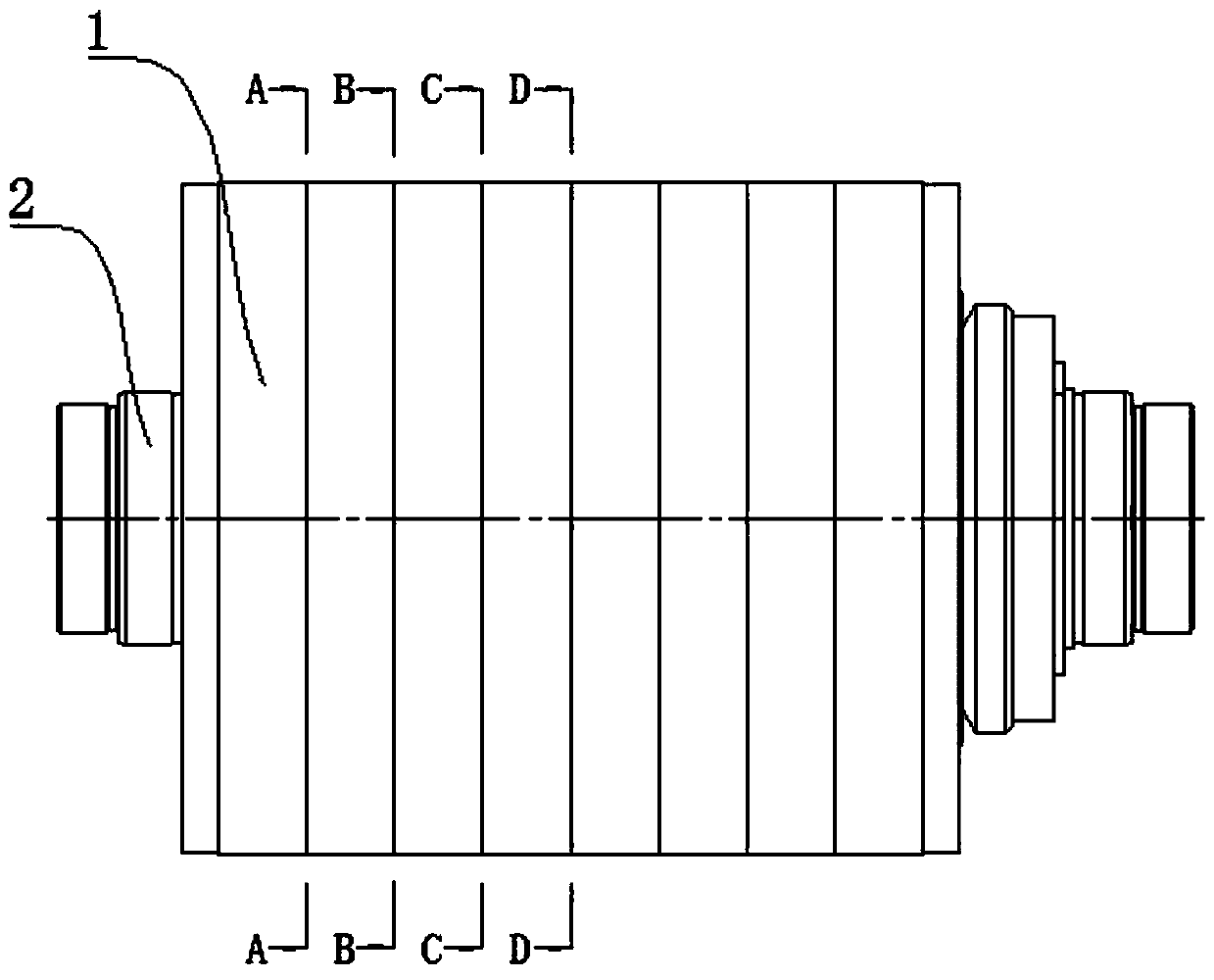
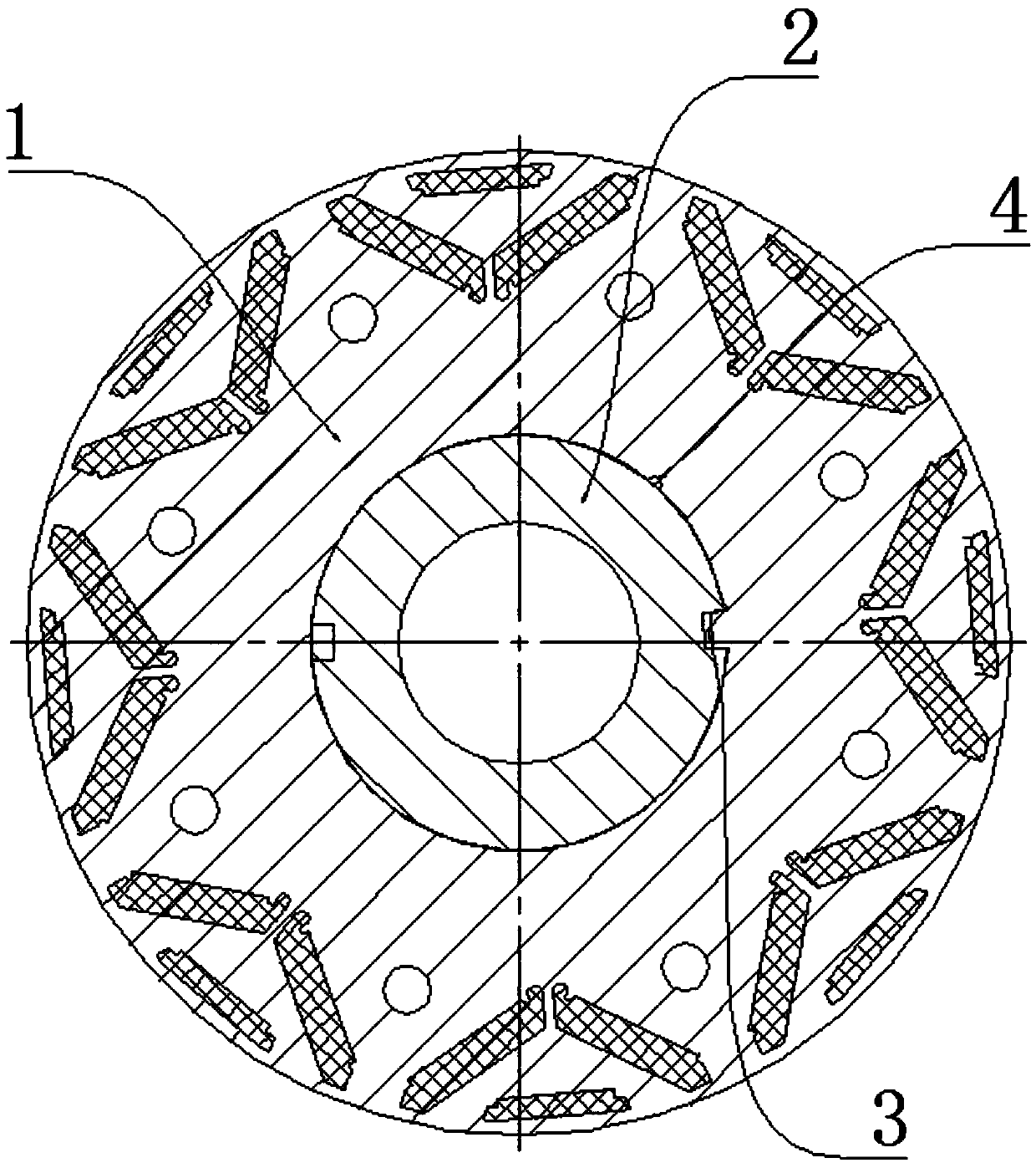
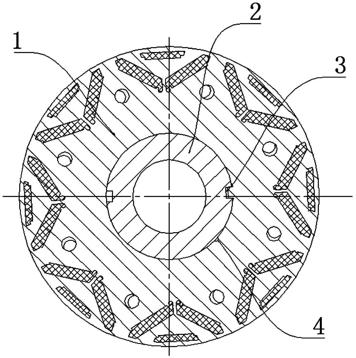
[0026] The reference signs in the drawings of the specification include: rotor core 1 , rotating shaft 2 , key groove 3 , and symbol groove 4 .

[0027] The embodiment is basically as attached figure 1 Shown: The permanent magnet motor rotor skew method, including the following steps:

[0028] A. Machining two asymmetric key grooves 3 on the rotating shaft 2 of the rotor;

[0029] B. Use rotor punches to form eight sections of rotor core 1, and each section of rotor core 1 is cylindrical. Select every two sections of rotor core 1 as a pair, and select two pairs of rotor cores 1 as a group. The marking groove 4 is processed at the same position on the inner wall of the shaft hole of each rotor core 1, and the marking groove 4 is a semicircular groove;

[0030] C. Install two groups of rotor cores 1 symmetrically on the rotating shaft 2, and install the two rotor cores 1 of each pai...


PUM


Abstract

The invention discloses an oblique pole method of a permanent-magnet motor rotor in the technical field of permanent-magnet motor rotors. The oblique pole method comprises the following steps of A, forming a plurality of non-asymmetric key slots in a rotation shaft of a rotor; B, forming a multi-segment rotor core from rotor punching sheets, wherein each two segments of rotor cores are selected tobe a pair, and even pairs of rotor cores are selected to form a group; C, symmetrically arranging the even numbers of rotor cores on the rotation shaft, wherein two segments of rotor cores of each pair are arranged in the same key slot; and D, deflecting two adjacent rotor cores in each group by a certain angle. By the oblique pole method, tooth harmonic can be reduced, the motor cogging torque and the torque ripple are improved, and unfavorable influence brought by cogging torque during the application process of an existing permanent-magnet motor is improved.

Description

technical field [0001] The invention relates to the technical field of permanent magnet synchronous motors, in particular to a method for oblique poles of a permanent magnet motor rotor. Background technique [0002] Compared with the traditional excitation motor, the permanent magnet motor has the remarkable characteristics of simple structure, small loss, high power factor, high efficiency, high power density, large starting torque, low temperature rise, and light weight. With the continuous improvement and improvement of the magnetic properties of rare earth permanent magnet materials (especially NdFeB permanent magnet materials) and the gradual reduction of prices, the research and development of permanent magnet motors has gradually matured, making permanent magnet motors widely used in national defense, industrial and agricultural production and daily life. etc. have been more and more widely used. [0003] Different from other types of motors, the main magnetic field...

Claims


Application Information

Patent Timeline
IPC IPC(8): H02K1/27
CPCH02K1/272H02K2213/03
Inventor 汪同斌
Owner CHONGQING ELECTRIC MACHINE FEDERATION
Why Eureka
Try Eureka