The positioning structure of the implant

A positioning structure and implant technology, which is applied in the field of orthopedic medical equipment technology and equipment, can solve problems such as the adjustment of fixing methods, and achieve the effect of balanced force and difficult position deviation

Active Publication Date: 2021-12-24
CHUANG MEI DE MEDICAL DEVICE TIANJIN CO LTD
View PDF7 Cites 0 Cited by
  • Summary
  • Abstract
  • Description
  • Claims
  • Application Information

AI Technical Summary

Problems solved by technology

During surgery, the implant is generally fixedly connected to the supporting stable bone body through the positioning structure of the implant. The positioning structure of the implant in the prior art includes the interconnected stable bone fixation part and the implanted bone body. The object supporting part, wherein the stabilizing bone fixing part is a U-shaped structure, which includes a bottom end and an open end, and the stabilizing bone fixing part is fixed to the bone body of the stabilizing bone, and the two implant supporting parts are correspondingly arranged on the stabilizing bone fixing part The open end of the implant support part is bent to form a support arm. In use, the support arm is inserted into the gap between the bone body of the stable bone and the implant, and the position of the implant is limited by the support arm, but Because the individual conditions of different fracture patients are not the same, the size, shape, fixed position and angle of the implant are also various, so a variety of implant positioning devices with different specifications are required, and they cannot be replaced unless they are replaced during the operation. Adjust the fixed mode according to the actual situation

Method used


Image

  • The positioning structure of the implant
  • The positioning structure of the implant
  • The positioning structure of the implant

Examples


Embodiment Construction

[0019] The technical solution of the present invention will be described in detail below with reference to the drawings and specific embodiments.

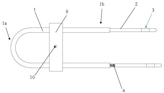
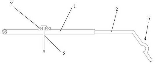
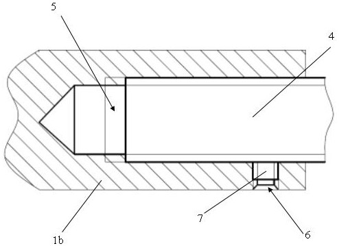
[0020] Such as Figure 1 to Figure 3 As shown, the positioning structure of the implant of the present invention includes a stable bone fixation part 1 and an implant support part 2 connected to each other, wherein the stable bone fixation part is a U-shaped structure, which also includes a bottom end 1a and an open end 1b , and the stable bone fixation part is fixed with the bone body of the stable bone, the two implant support parts are correspondingly arranged at the opening end of the stable bone fixation part, and the top end of the implant support part is bent to form a support arm 3, the support arm is Arched structure, the support arm is inserted into the gap between the bone body of the stable bone and the implant during use, and the position of the implant is restricted by the support arm. The implant support part and the...


PUM


Abstract

A positioning structure for an implant, comprising an interconnected stable bone fixation part and an implant support part, wherein the stable bone fixation part is a U-shaped structure, which further includes a bottom end and an open end, and the stable bone fixation part and the stable bone fixation part The bone body of the bone is fixed, and the two implant supporting parts are correspondingly arranged at the opening end of the stabilizing bone fixing part, and the top end of the implant supporting part is bent to form a supporting arm, and the supporting arm is inserted into the bone body of the stabilizing bone and the implant In the gap between them, the position of the implant is limited by the support arm, the implant support part and the stable bone fixation part are split structures, and the torsion angle between the implant support part and the stable bone fixation part is selectively set , to change the setting angle of the head end of the implant support part, so as to meet the fixing requirements of various implants, make the force between the implant and the implant support part more balanced, and prevent positional deviation .

Description

technical field [0001] The invention relates to the technical field of orthopedic medical equipment, in particular to an implant positioning structure in orthopedic surgery. [0002] technical background [0003] Fracture is one of the most common injuries. In orthopedic surgery, it is necessary to use orthopedic instruments to reconstruct the bone body after fracture and restore it to a normal state. Orthopedic implants are one of the most commonly used orthopedic instruments. During surgery, the implant is generally fixedly connected to the supporting stable bone body through the positioning structure of the implant. The positioning structure of the implant in the prior art includes the interconnected stable bone fixation part and the implanted bone body. The object supporting part, wherein the stabilizing bone fixing part is a U-shaped structure, which includes a bottom end and an open end, and the stabilizing bone fixing part is fixed to the bone body of the stabilizing b...

Claims


Application Information

Patent Timeline
Patent Type & Authority Patents(China)
IPC IPC(8): A61B17/68A61B17/86A61B17/88
CPCA61B17/683A61B17/8625A61B17/8888A61B17/8894
Inventor 潘兵辉
Owner CHUANG MEI DE MEDICAL DEVICE TIANJIN CO LTD
Why Eureka
Try Eureka