Rib punching die

A mold and bead punching technology, which is applied in the field of molds, can solve the problems of high processing cost and low efficiency of bead punching on the surface of cup tubes.

Pending Publication Date: 2019-04-16
ZHEJIANG HAERS VACUUM CONTAINERS CO LTD
View PDF0 Cites 4 Cited by
  • Summary
  • Abstract
  • Description
  • Claims
  • Application Information

AI Technical Summary

Problems solved by technology

[0003] The invention provides a new bead punching die for the defects of low bead punching efficiency and high processing cost on the surface of the cup tube existing in the prior art

Method used


Image

  • Rib punching die
  • Rib punching die
  • Rib punching die

Examples


Embodiment 1

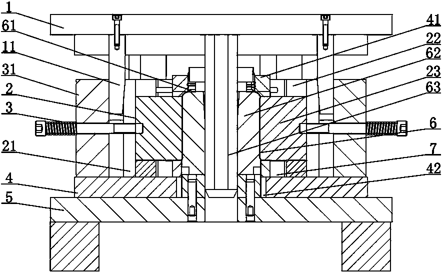
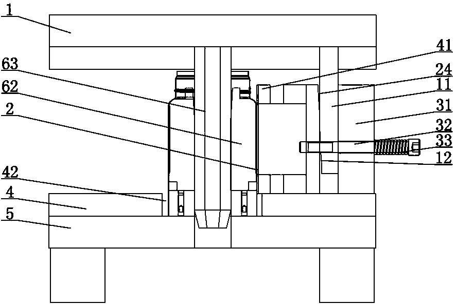
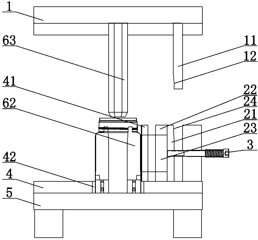
[0032] A bead punching die, comprising an upper mold base 1, a lower mold base 5, a punch assembly 2, a punch table 4, a support assembly 6, and a punch reset assembly 3, and the punch table 4 is arranged on the lower mold base 5, the punch table 4 is provided with a housing chamber 42, the punch assembly 2 surrounds the housing chamber 42 in an annular array, the support assembly 6 is arranged inside the housing chamber 42, and the punch resets The assembly 3 is connected to the punch assembly 2 and provides an outward restoring force for the punch assembly 2. The upper die base 1 is provided with a side insertion knife 11. When the upper die base 1 moves downward , the side inserting knife 11 moves down and drives the punch assembly 2 to move inward, and when the upper die base 1 moves upward, the punch assembly 2 moves downward driven by the punch reset assembly 3 Move outside.

[0033] When in use, the cup tube is placed in the accommodating cavity 42, the upper die base ...


PUM


Abstract

The invention discloses a rib punching die comprising an upper die base and a lower die base, and further comprises puncher pin assemblies, a punching table, support assemblies and puncher pin resetting assemblies. The punching table is arranged on the lower die base, the punching table is provided with a containing cavity, the puncher pin assemblies surround the containing cavity in an annular array manner, the support assemblies are arranged on the inner side of the containing cavity, the puncher pin resetting assemblies are connected to the puncher pin assemblies and provide outward restoring force to the puncher pin assemblies, the upper die base is provided with a side inserting knife, when the upper die base moves downwards, the side inserting knife moves downwards and drives the puncher pin assemblies to move inwards, and when the upper die base moves upwards, the puncher pin assemblies are driven by the puncher pin resetting assemblies to move outwards. According to the rib punching die, through the puncher pin assemblies arranged in the annular array and surrounding manners, rib punching is carried out on the surface of a cup tube, and the rib punching processing efficiency is improved.

Description

technical field [0001] The invention relates to a mold, in particular to a bead punching mold. Background technique [0002] In the process of cup tube processing, it is often necessary to punch ribs on the cup tube to improve the structural strength and aesthetic appearance of the cup tube. However, the existing rib punching mold has a single structure and can only punch out a rib on the surface of the cup tube. , the processing efficiency is low, and the processing cost is also high, which needs to be improved. Contents of the invention [0003] The invention provides a new bead punching mold aiming at the defects of low bead punching efficiency and high processing cost on the surface of the cup tube existing in the prior art. [0004] In order to solve the above technical problems, the present invention is realized through the following technical solutions: [0005] A bead punching die, comprising an upper mold base, a lower mold base, and a punch assembly, a punch ta...

Claims


Application Information

Patent Timeline
Patent Type & Authority Applications(China)
IPC IPC(8): B21D15/02B21D37/10
CPCB21D15/02B21D37/10
Inventor 翁文武吴伟汪宝林
Owner ZHEJIANG HAERS VACUUM CONTAINERS CO LTD
Why Eureka
Try Eureka