
Hydraulic piston machine, in particular water hydraulic machine

a technology of hydraulic piston machine and water pump, which is applied in the direction of mechanical equipment, pumps, engines with rotating cylinders, etc., can solve the problems of loss, loss, and loosing of holding ability, and achieves the effect of small risk of damaging the filling member during the insertion and simple insertion of the filling member

Active Publication Date: 2011-06-09
DANFOSS AS
View PDF19 Cites 2 Cited by
  • Summary
  • Abstract
  • Description
  • Claims
  • Application Information

AI Technical Summary

Benefits of technology

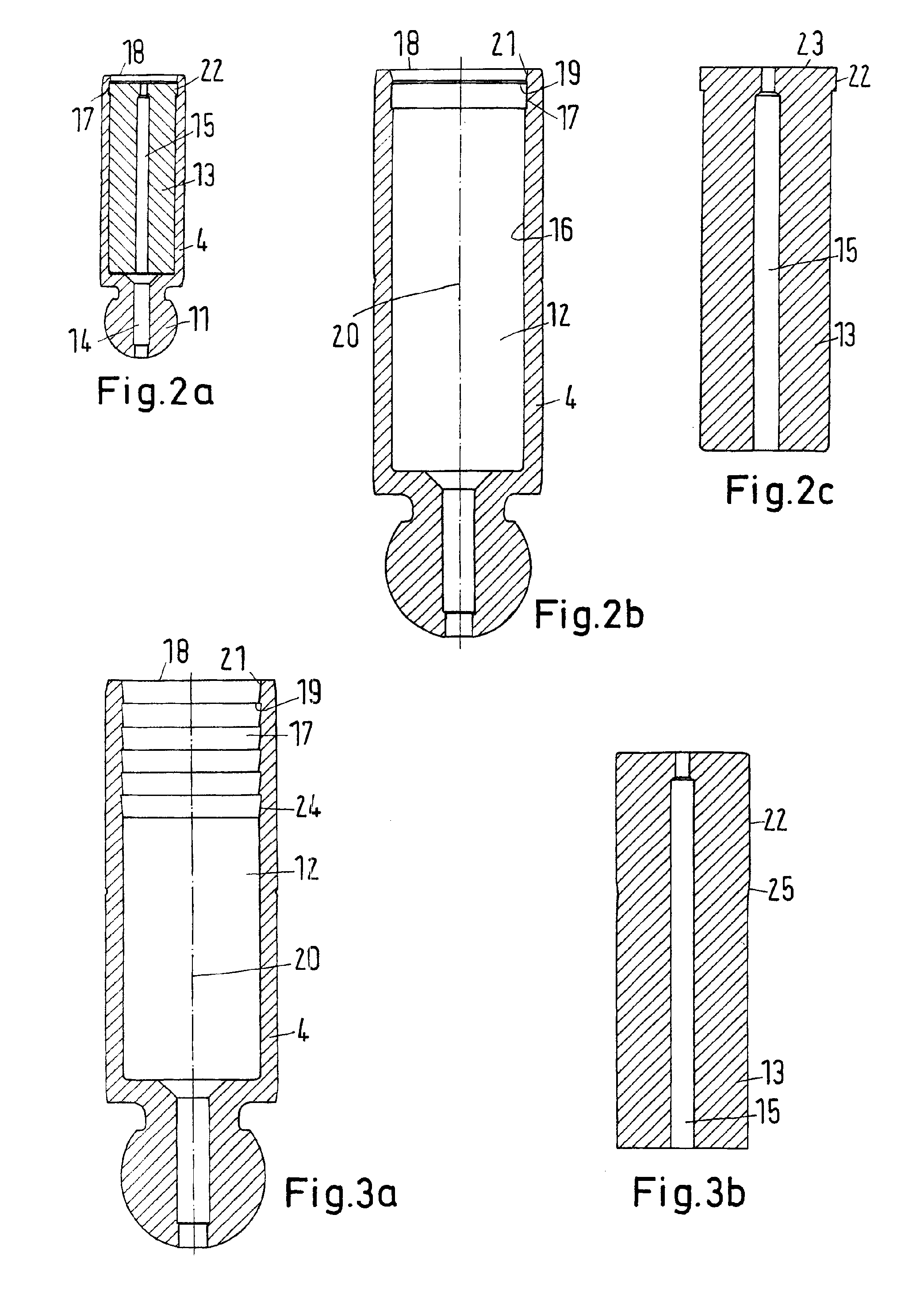
[0007]This embodiment permits the use of a filling member inside the piston, which will, in the ideal case, prevent liquid, in particular water, from entering the hollow and causing cavitations in connection with occurring underpressures. However, already a reduction of the amount of water entering the hollow will reduce the cavitations. The special adaptation of piston and filling member to one another makes the manufacturing simple. The filling member can simply be pressed into the piston. After insertion of the filling member into the piston, the filling member is held in the piston by means of form-fit, without requiring further fixing elements. In particular in connection with water as hydraulic fluid, fixing elements of metal tend to cause problems. They suffer from corrosion and after a certain operation duration they may even loose their holding ability.
[0012]Further, it is advantageous, when the projection is uninterrupted in the circumferential direction. In this case, the whole circumference of the filling member is used to provide the desired holding force for the filling member in the piston.
[0013]Preferably, the restraint is made as a step. Such a step provides sufficient resistance against a movement of the filling member out of the piston. The projection of the filling member bears on the step, thus preventing an outward movement of the filling member. The same applies, when the projection has been made on the annular wall.
[0015]Preferably, the free end of the hollow has a conical bulge. This simplifies the insertion of the filling member. The conical bulge causes that at least the projection of the filling member is compressed radially during insertion into the hollow. As soon as the hollow reaches the depression, the projection can expand radially again, and the filling member is held in the piston by means of form-fit.
[0016]Preferably, the projection, together with the end of the filling member adjacent to the free end of the hollow, forms a common front face. Thus, on this front face the filling member has not step. The consequence of this is that after the insertion the filling member is somewhat recessed in relation to the open end of the piston. However, when inserting the filling member into the piston the required forces can be applied to the filling member over a relatively large cross-sectional face, so that the risk of damaging the filling member during the insertion is small.

Problems solved by technology

In particular in connection with water as hydraulic fluid, fixing elements of metal tend to cause problems.
They suffer from corrosion and after a certain operation duration they may even loose their holding ability.
Here, however, the compressibility is usually larger.
Thus, also the losses get larger and with oil hydraulic machines, it is endeavoured to reduce the dead volume by means of the filling member.
As mentioned above, however, such a cup spring is in danger of getting corroded.

Method used


Image

  • Hydraulic piston machine, in particular water hydraulic machine
  • Hydraulic piston machine, in particular water hydraulic machine
  • Hydraulic piston machine, in particular water hydraulic machine

Examples


Embodiment Construction

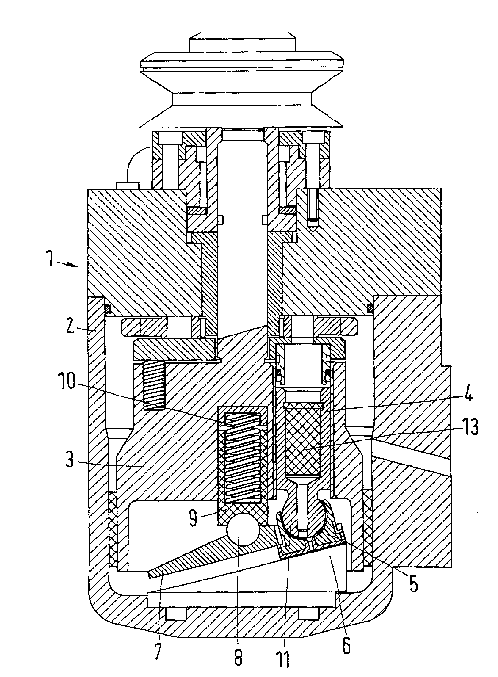
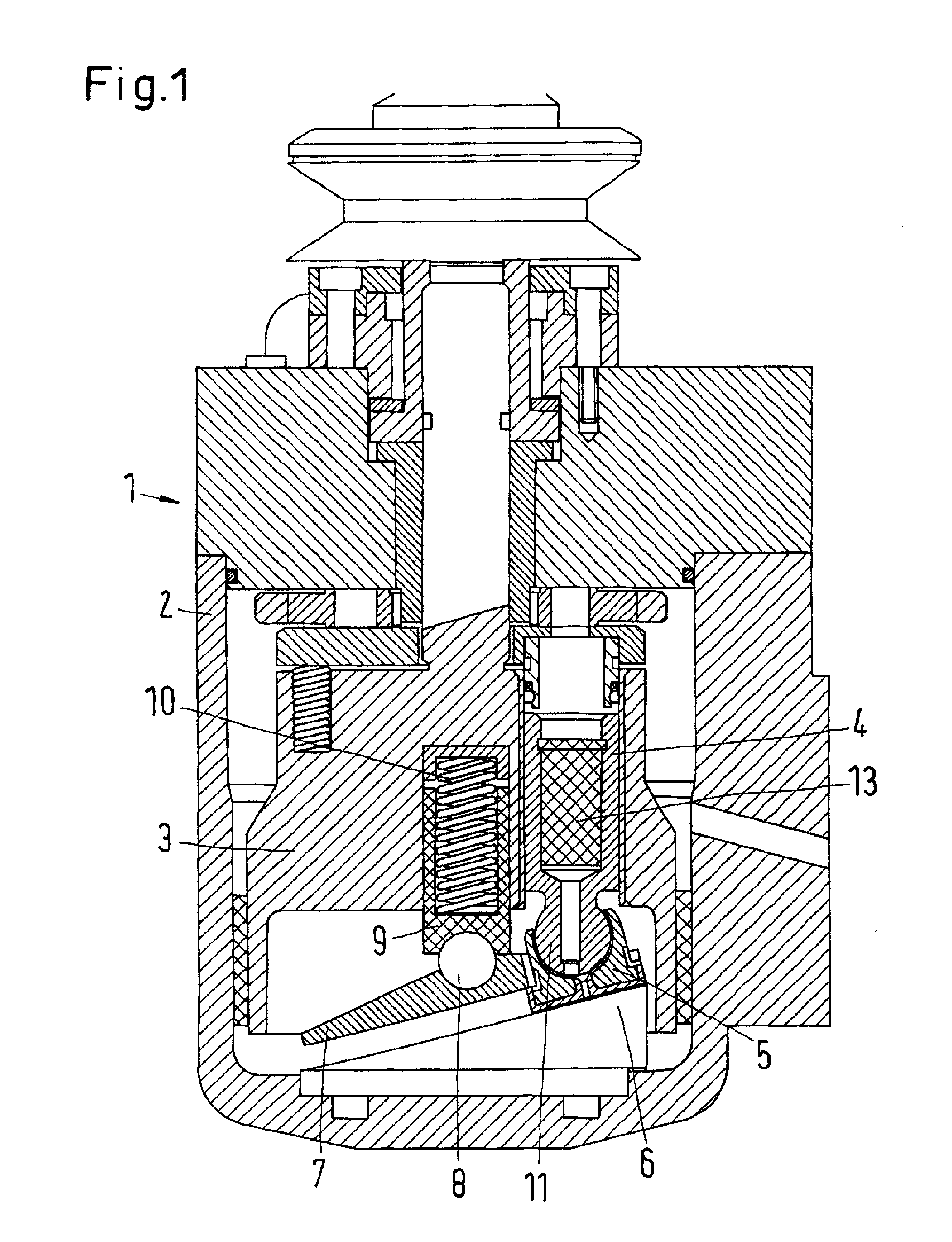
[0024]A hydraulic axial piston machine 1 comprises a cylinder drum 3 that is arranged to be rotatable in a housing 2. In the cylinder drum 3, pistons 4 are arranged to be movable in the axial direction. Only one piston 4 is visible. All other pistons are located outside the sectional plane. The pistons 4 are guided on a wobble plate 6 by means of a slide shoe 5. A pressure plate 7 holds the slide shoe 5 in a bearing position against the wobble plate 6. Via a ball 8, the pressure plate bears on one end of a pressure piston 9 that is accommodated in the cylinder drum. The pressure piston 9 is acted upon in the axial direction by a spring 10, meaning that it is pressed in the direction of the wobble plate 6.

[0025]Preferably, the piston 4 is made of stainless steel. In dependence of the conditions, under which the machine will be used, in particular the pressures, media and designs, also other materials can be used, in particular plastic.

[0026]As known per se, a rotation of the cylinder...


PUM


Abstract

The invention concerns a hydraulic piston machine, in particular a water hydraulic machine, with at least one cylinder, in which a piston (4) is arranged to reciprocate, the piston (4) comprising a hollow that is surrounded by an annular wall and has one open end. It is endeavoured to keep cavitations small. For this purpose, a filling member (13) is arranged in the hollow (12), the filling member (13) having at least a radial projection (22) and the annular wall (16) having at least a radial depression (17) in the inside facing the hollow (12), or the annular wall (16) having a radial projection and the filing member (13) having a radial depression, the depression having a restraint (19), at least at the end adjacent to the open end (18) of the hollow (12), and the projection (22) and the depression (17) engaging each other.

Description

CROSS REFERENCE TO RELATED APPLICATIONS[0001]Applicant hereby claims foreign priority benefits under U.S.C. §119 from German Patent Application No. 10 2009 056 903.0 filed on Dec. 3, 2009, the contents of which are incorporated by reference herein.TECHNICAL FIELD[0002]The invention concerns a hydraulic piston machine, in particular a water hydraulic machine, with at least one cylinder, in which a piston is arranged to reciprocate, the piston comprising a hollow that is surrounded by an annular wall and has one open end.BACKGROUND OF THE INVENTION[0003]Such a piston machine is known from DE 10 2004 043 745 B3.[0004]The hollow of the piston is advantageous, as it reduces the mass of the piston, when compared to a massive piston. When, however, such a piston machine is used as a pump for water, it can be observed that cavitations occur in the hollow. It is assumed that the underpressure gets too large, as the fluid cannot be moved fast enough.SUMMARY OF THE INVENTION[0005]The invention...

Claims


Application Information

Patent Timeline
IPC IPC(8): F04B1/12F04B1/20F01B3/00F16J1/00
CPCF04B1/2014F04B1/124F01B3/0085
Inventor HANSEN, OVE THORBOEL
Owner DANFOSS AS
Learn More