
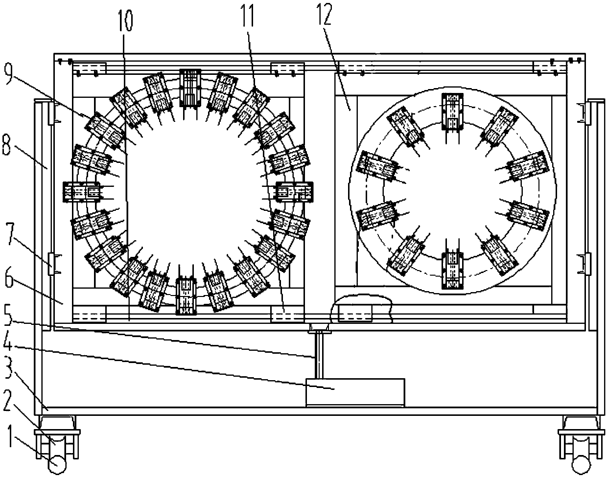
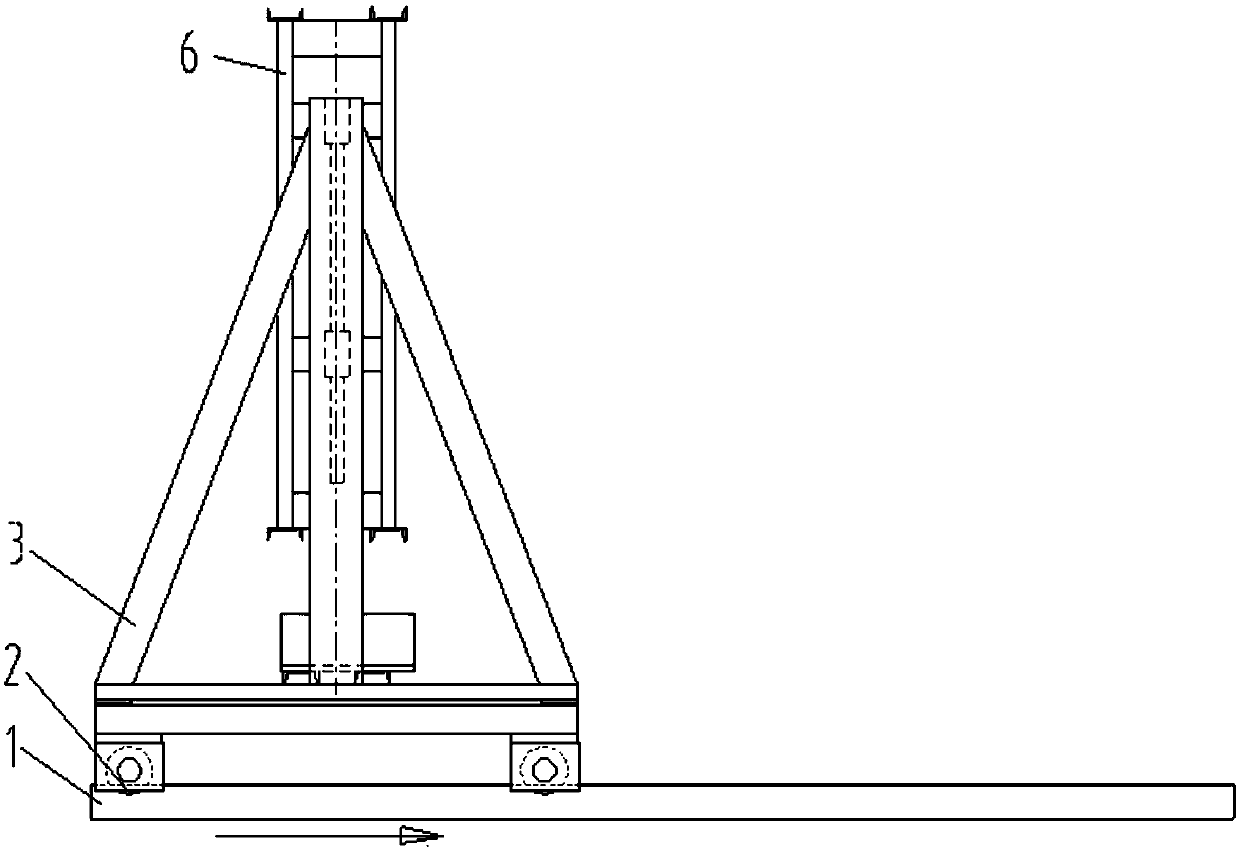
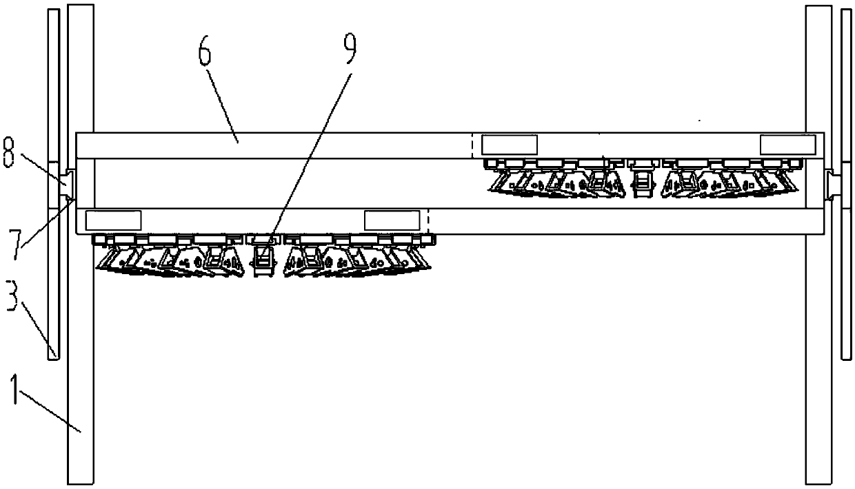
Circular rubber pipe orifice expanding device

A rubber tube and circular technology, applied in the field of insulation tube production equipment, can solve the problems of low use efficiency, time-consuming and labor-intensive, high failure rate, etc., achieve stable work, wide application range, and prevent the effect of falling off during movement

Pending Publication Date: 2019-04-16
天津市九赢百信科技有限公司
View PDF7 Cites 0 Cited by
  • Summary
  • Abstract
  • Description
  • Claims
  • Application Information

AI Technical Summary

Problems solved by technology

[0002] In the current pipeline industry, in the production process of the insulation pipe, the steel pipe penetrates the deformed rubber tube and regularly places the support block on the iron pipe. There are three operation modes: Mode 1. The deformed rubber tube is placed On the frame, the steel pipe to be penetrated is placed on the automatic forward transmission frame in a straight line with the rubber pipe frame. When the steel pipe is about to enter the rubber pipe, after the support block is attached to the steel pipe, the deformation is manually deformed. The mouth of the rubber pipe is lifted one by one, so that the iron pipe with the support block can enter the rubber pipe, so that each set of support blocks must be manually lifted one by one when entering the deformed rubber pipe mouth, which is time-consuming and laborious; A guide head is installed on the top of the buckle to guide the head of the steel pipe into the deformed rubber tube. However, when the support block at the back enters the deformed rubber tube, it still cannot enter the deformed rubber tube smoothly. Tilt up to allow each group of support blocks to enter; method three, the support arm support mechanism, this mechanism is to make the support blocks provided on the outer circumference of the steel pipe pass through the intervals between multiple sets of support arms, because the highest point of the support block and The distance between the inner walls of the stretched rubber tubes is very small, about 2 millimeters. If the distance between the support arms is too large, it will be difficult for the support blocks to enter the rubber tubes; the existing three methods are too efficient in use. low, the failure rate is too high

Method used


Image

  • Circular rubber pipe orifice expanding device
  • Circular rubber pipe orifice expanding device
  • Circular rubber pipe orifice expanding device

Examples


Embodiment Construction

[0027] It should be noted that, in the case of no conflict, the embodiments of the present invention and the features in the embodiments can be combined with each other.

[0028] In describing the present invention, it should be understood that the terms "center", "longitudinal", "transverse", "upper", "lower", "front", "rear", "left", "right", " The orientations or positional relationships indicated by "vertical", "horizontal", "top", "bottom", "inner" and "outer" are based on the orientations or positional relationships shown in the drawings, and are only for the convenience of describing the present invention and Simplified descriptions, rather than indicating or implying that the device or element referred to must have a particular orientation, be constructed and operate in a particular orientation, and thus should not be construed as limiting the invention. In addition, the terms "first", "second", etc. are used for descriptive purposes only, and should not be understood ...


PUM


Abstract

The invention provides a circular rubber pipe orifice expanding device. The device comprises a frame; the frame is slidingly connected with a lifting frame; the lifting frame is provided with multiplesets of support frames arranged in parallel; the support frames are slidingly connected with orifice expanding mechanisms; the orifice expanding mechanisms slide between two opposite side walls of the support frames; the sliding directions of the orifice expanding mechanisms are perpendicular to the arrangement direction of the multiple support frames; and motions of the orifice expanding mechanisms on all the support frames are independent. The circular rubber pipe orifice expanding device realizes machining of pipes with different specifications through simple structure cooperation by adopting an automatic mode, and realizes mutual switching operation of multiple pipe diameters.

Description

technical field [0001] The invention belongs to the technical field of insulation pipe manufacturing devices, and in particular relates to a circular rubber pipe opening device. Background technique [0002] In the current pipeline industry, in the production process of the insulation pipe, the steel pipe penetrates the deformed rubber tube and regularly places the support block on the iron pipe. There are three operation modes: Mode 1. The deformed rubber tube is placed On the frame, the steel pipe to be penetrated is placed on the automatic forward transmission frame in a straight line with the rubber pipe frame. When the steel pipe is about to enter the rubber pipe, after the support block is bonded on the steel pipe, the deformation is manually deformed. The mouth of the rubber pipe is tilted up one by one, so that the iron pipe with the support block enters the rubber pipe, so that each set of support blocks must be manually lifted one by one when entering the deformed ...

Claims


Application Information

Patent Timeline
IPC IPC(8): B29C57/04
CPCB29C57/04
Inventor 李刚
Owner 天津市九赢百信科技有限公司
Learn More