A friction coupling for a rail transit switch machine

A technology of friction coupling and rail transit, applied in the direction of electrical equipment used to manipulate turnouts or line breakers, railway signals, railway signals and safety, etc., can solve problems such as difficulty in separation, and achieve the effect of large initial resistance value

Active Publication Date: 2021-03-09
江苏亚太特种铸钢厂有限公司
View PDF6 Cites 0 Cited by
  • Summary
  • Abstract
  • Description
  • Claims
  • Application Information

AI Technical Summary

Problems solved by technology

[0005] Aiming at the deficiencies in the use of the existing friction couplings in point machines proposed in the background technology, the present invention provides a friction coupling for rail transit point machines, which has inner and outer friction plates that move relative to each other in a timely manner, friction The coefficient is relatively stable, which solves the problem that the inner and outer friction plates are stuck together for a long time and are difficult to separate due to corrosion.

Method used


Image

  • A friction coupling for a rail transit switch machine
  • A friction coupling for a rail transit switch machine
  • A friction coupling for a rail transit switch machine

Examples


Embodiment Construction

[0019] The following will clearly and completely describe the technical solutions in the embodiments of the present invention with reference to the accompanying drawings in the embodiments of the present invention. Obviously, the described embodiments are only some, not all, embodiments of the present invention. Based on the embodiments of the present invention, all other embodiments obtained by persons of ordinary skill in the art without making creative efforts belong to the protection scope of the present invention.

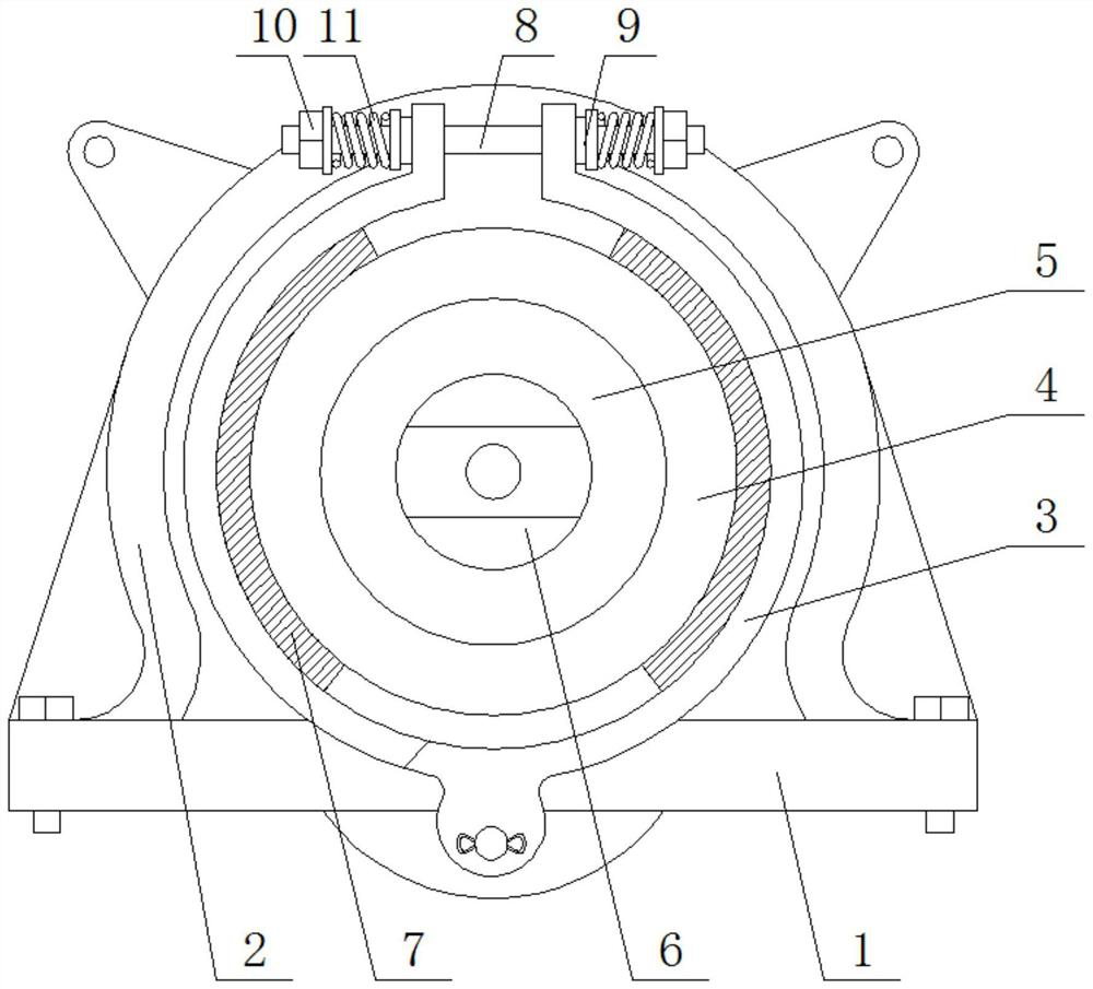
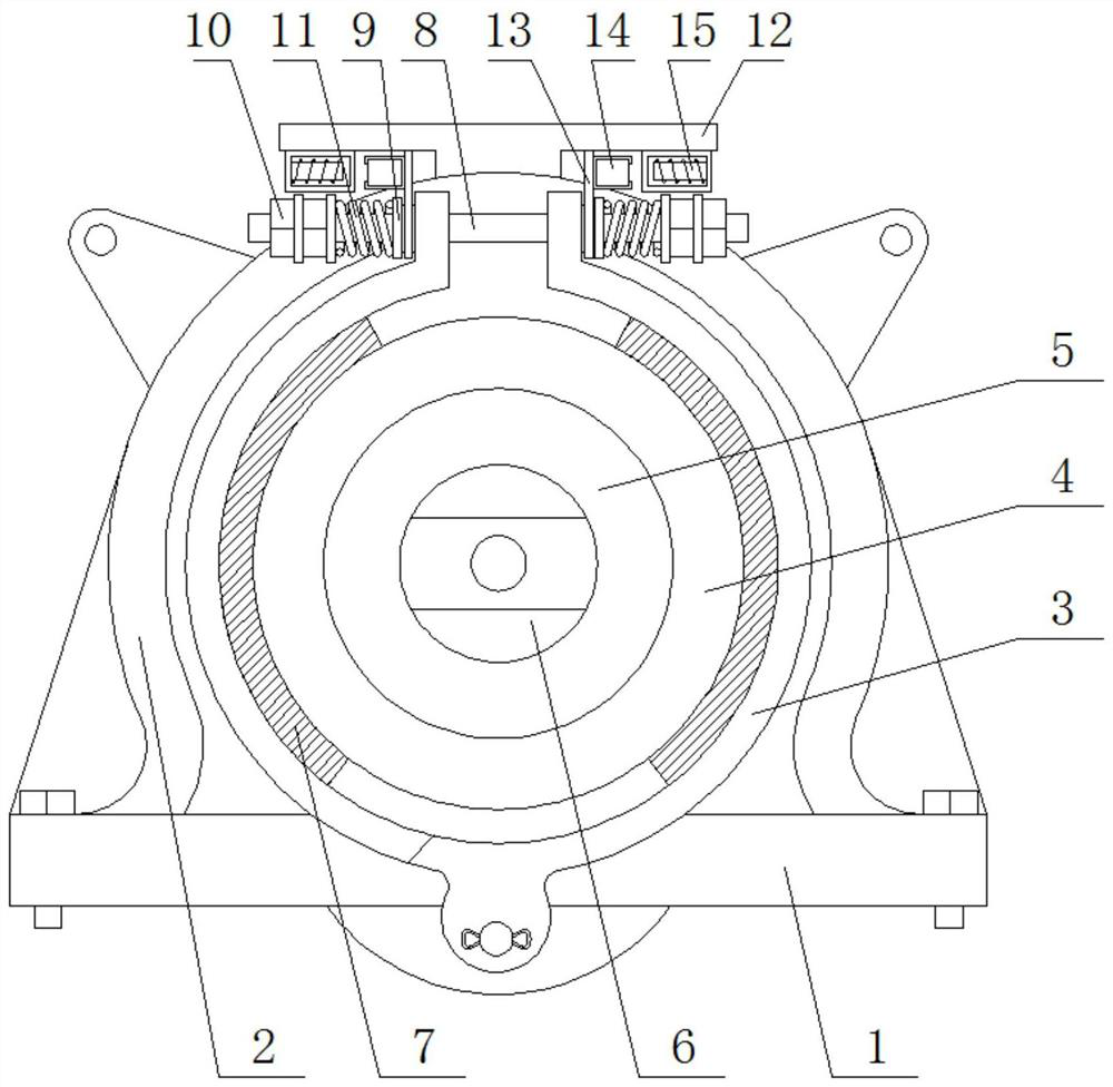
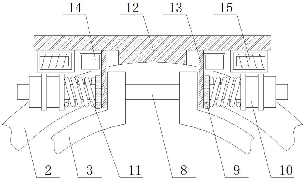
[0020] see Figure 1-4 , a friction coupling for a rail transit switch machine, comprising a base 1, a deceleration case 2 is fixedly mounted on the top of the base 1, a friction brake plate 3 is hinged on the front of the base 1, and the inside of the friction brake plate 3 An internal gear 4 is provided, and the internal gear 4 is fixedly sleeved with a ball bearing 5, and the internal sleeve of the ball bearing 5 is fixedly sleeved with an output shaft 6. T...


PUM


Abstract

The invention relates to the technical field of rail transit equipment, and discloses a friction coupling for a rail transit switch machine, which includes a base, a deceleration shell is fixedly installed on the top of the base, and a friction brake plate is hinged on the front of the base. An internal gear is arranged inside the braking plate, and a ball bearing is fixedly sleeved inside the internal gear. The present invention arranges permanent magnets and electromagnets. When the AC motor is powered off, the electromagnets are energized to attract the permanent magnets to move toward each other, and the connecting plate compresses and adjusts the spring through the gasket, so that the pressure of the friction brake plate is removed, thereby releasing the friction. The friction connection performance between the brake plate and the internal gear makes the friction brake plate and the internal gear rotate relative to each other under the action of inertial force, that is, after the switch machine completes each normal switching action task, the friction brake plate There will be a relative rotation with the internal gear, which effectively avoids the problem that the friction brake plate and the internal gear are difficult to separate after being rusted and bonded due to long-term bonding.

Description

technical field [0001] The invention relates to the technical field of rail transit equipment, in particular to a friction coupling for a rail transit switch machine. Background technique [0002] The switch machine is an important driving control device in the field of rail transit. It is used to reliably change the position of the switch, change the opening direction of the switch, lock the point rail of the switch, and reflect the signal of the position of the switch. According to the action energy and transmission mode, it can be divided into electric switch machines, electro-pneumatic switch machines and electro-hydraulic switch machines. Among them, electric switch machines can be divided into DC switch machines and AC switch machines according to the type of power supply. However, due to the existence of commutators and brushes, DC motors are easily damaged and have a high failure rate. Therefore, AC motors are mostly used as power devices. [0003] In the AC point m...

Claims


Application Information

Patent Timeline
Patent Type & Authority Patents(China)
IPC IPC(8): B61L5/06
CPCB61L5/065
Inventor 不公告发明人
Owner 江苏亚太特种铸钢厂有限公司
Why Eureka
Try Eureka