Unpowered ventilation device and tunnel

A technology of power ventilation and ventilation pipes, which is applied in the direction of pump devices, mechanical power transmission, mine/tunnel ventilation, etc., and can solve the problems of poor health of passing personnel, high power consumption, and inability to meet the ventilation requirements of the tunnel body.

Pending Publication Date: 2019-04-16
GUANGZHOU ENG CO LTD OF CHINA RAILWAY 19TH BUREAU GRP
View PDF0 Cites 0 Cited by
  • Summary
  • Abstract
  • Description
  • Claims
  • Application Information

AI Technical Summary

Problems solved by technology

[0002] The air retention in the tunnel body will seriously affect the air quality in the inner cavity of the tunnel body, which is unfavorable to the health of passers-by, especially for some narrow and long tunnel bodies, the deeper the inner cavity of the tunnel body is, the more air in the inner cavity of the tunnel body will be. less gas exchange between the air and the atmosphere outside the tunnel body, resulting in poorer air quality in the inner cavity of the tunnel body
[0003] In order to solve the above problems, various ventilation devices have been proposed in the prior art. However, most of the existing ventilation devices rely on external electric power to drive fans to ventilate the tunnel body. The cost of traffic operation is poor, and the economy is poor; there are also some ventilation devices without external drive, and their ventilation capacity is very weak, which cannot meet the ventilation requirements of the tunnel body

Method used


Image

  • Unpowered ventilation device and tunnel
  • Unpowered ventilation device and tunnel
  • Unpowered ventilation device and tunnel

Examples


Embodiment 1

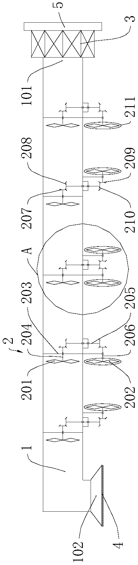
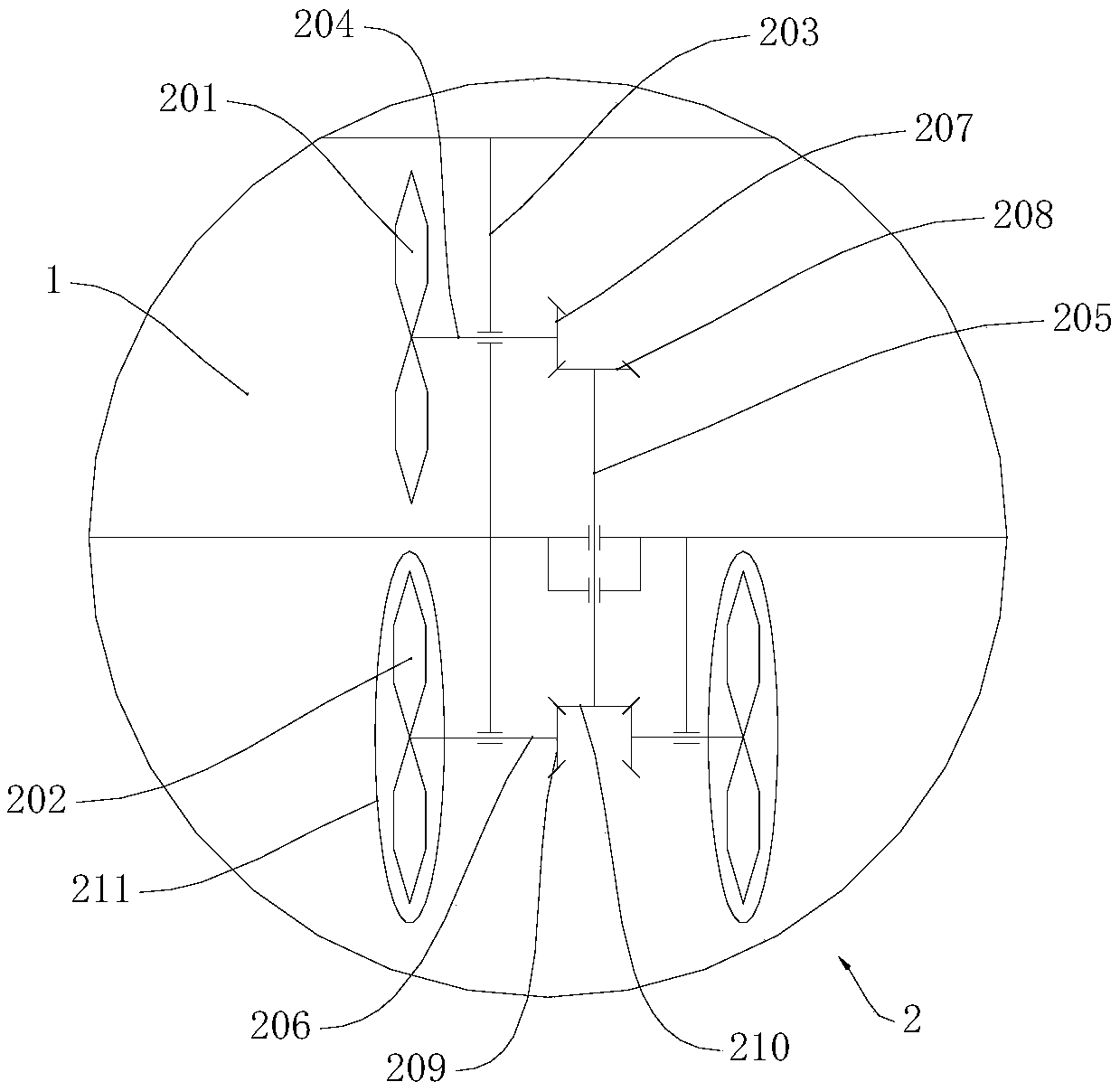
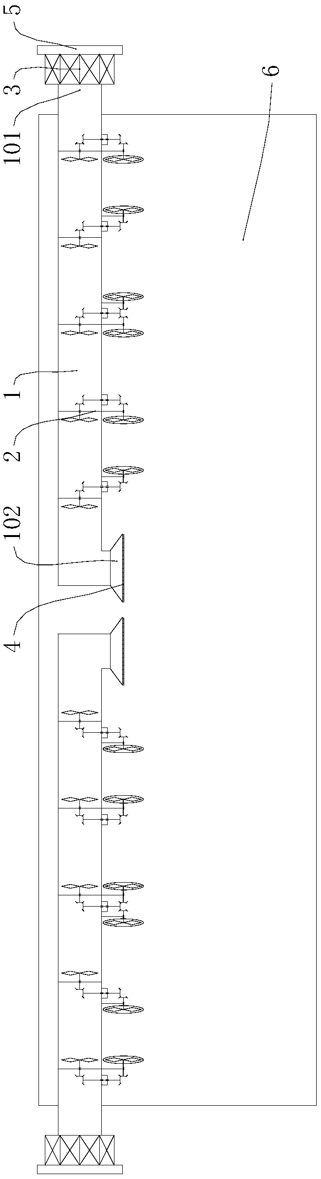
[0044] see image 3, the tunnel of this embodiment includes the tunnel body 6 and the aforementioned unpowered ventilation device, the ventilation duct 1 is arranged along the extension direction of the tunnel body 6, the first tuyere 101 is located outside the tunnel body 6, and the second tuyere 102 is located inside the tunnel body 6 In the cavity, the second rotating fan 202 is located in the inner cavity of the tunnel body 6 , and the wind receiving direction of the second rotating fan 202 is along the extending direction of the tunnel body 6 . Because the tunnel body 6 is generally a long and narrow space, the closer to the exit of the tunnel body 6 in the long and narrow space of the tunnel body 6, the more the gas exchanges with the gas outside the tunnel body 6, and the farther away from the position of the exit of the tunnel body 6, the more The less the gas exchanges with the gas outside the tunnel body 6; the worse the gas quality is at the position farther away fr...

Embodiment 2

[0051] The tunnel provided in this embodiment includes a tunnel body 6 and two sets of the aforementioned unpowered ventilation devices, each ventilation duct 1 is arranged along the extension direction of the tunnel body 6, and each ventilation duct 1 communicates with the inner cavity of the tunnel body 6 and the tunnel body 6 external environment; each second rotating fan 202 is located in the cavity of the tunnel body 6, and the fanning direction of each second rotating fan 202 is along the extension direction of the tunnel body 6; The outside of the tunnel body 6 fans the wind in the direction of the inner cavity of the tunnel body 6 ; in another part of the non-powered ventilation device, the first rotating fan 201 fans the wind from the inner cavity of the tunnel body 6 to the direction outside the tunnel body 6 . A part of the non-powered ventilation device extracts the poor-quality gas in the inner cavity of the tunnel body 6 to the outside of the tunnel body 6, and an...


PUM


Abstract

The invention relates to the technical field of ventilation of mines or tunnels, and provides an unpowered ventilation device and tunnel, which comprise a ventilation duct and a blower assembly, wherein a first air inlet and a second air inlet are arranged on the ventilation duct; the blower assembly comprises a first rotary fan and a second rotary fan, the first rotary fan is arranged in an innercavity of the ventilation duct, a fan direction of the first rotary fan is in an extending direction of the ventilation duct, the second rotary fan is arranged outside the ventilation duct, the firstrotary fan is in transmission connection with the second rotary fan; and a one-way mechanism is arranged in a transmission chain from the first rotary fan to the second rotary fan. Under limitation of the one-way mechanism, the fan direction of the first rotary fan is fixed, so that an air flow direction of the ventilation duct is uniform, a repeated air flow direction in the ventilation duct isavoided, a stable air flow direction in the ventilation duct is guaranteed, thereby increasing quantity of air flow in the ventilation duct in unit time and further improving the ventilation capacityof the ventilation duct.

Description

technical field [0001] The invention relates to the technical field of ventilation in mines or tunnels, in particular to a non-powered ventilation device and a tunnel. Background technique [0002] The air retention in the tunnel body will seriously affect the air quality in the inner cavity of the tunnel body, which is unfavorable to the health of passers-by, especially for some narrow and long tunnel bodies, the deeper the inner cavity of the tunnel body is, the more air in the inner cavity of the tunnel body will be. The less gas exchange there is between the air and the atmosphere outside the tunnel body, resulting in poorer air quality in the inner cavity of the tunnel body. [0003] In order to solve the above problems, various ventilation devices have been proposed in the prior art. However, most of the existing ventilation devices rely on external electric power to drive fans to ventilate the tunnel body. The cost of transportation operation is poor, and the economy...

Claims


Application Information

Patent Timeline
Patent Type & Authority Applications(China)
IPC IPC(8): E21F1/08F04D25/04F04D25/16F03D9/28F03D15/00
CPCE21F1/08F03D9/28F03D15/00F04D25/045F04D25/166Y02E10/72
Inventor 蔡天成夏时光
Owner GUANGZHOU ENG CO LTD OF CHINA RAILWAY 19TH BUREAU GRP
Why Eureka
Try Eureka