Multifunctional aviation engine air inlet channel and running method thereof

A technology of aero-engine and operating method, which is applied in the direction of engine components, machine/engine, turbine/propulsion device air intake, etc., can solve the problems of aero-engine safe operation, inability to guarantee foreign object intrusion, air crash accidents, etc., to achieve The Effects of Premium Radar and Infrared Stealth Capabilities

Active Publication Date: 2019-04-16
SHENYANG LIMING AERO-ENGINE GROUP CORPORATION
View PDF5 Cites 5 Cited by
  • Summary
  • Abstract
  • Description
  • Claims
  • Application Information

AI Technical Summary

Problems solved by technology

[0003] Conventional aero-engine inlets are simple straight barrel structures, but they cannot achieve aircraft radar stealth. In order to achieve aircraft radar stealth, the current more advanced aero-engine inlets use S-shaped barrel structures. The radar wave disturbed by the compressor can block a part of the radar reflection wave after passing through the air inlet with special structure, so as to realize radar stealth
[0004] However, no matter it is the air inlet with conventional structure or the air inlet with radar stealth function, there is a weakness, that is, the intrusion of foreign objects, such as birds, sand and stones, cannot be guaranteed; once foreign objects are sucked into the air inlet, it will damage the The safe operation of aero-engines has a major impact, and in serious cases can directly lead to engine failure and even serious air accidents

Method used


Image

  • Multifunctional aviation engine air inlet channel and running method thereof

Examples


Embodiment Construction

[0015] The present invention will be further described in detail below in conjunction with the accompanying drawings and specific embodiments.

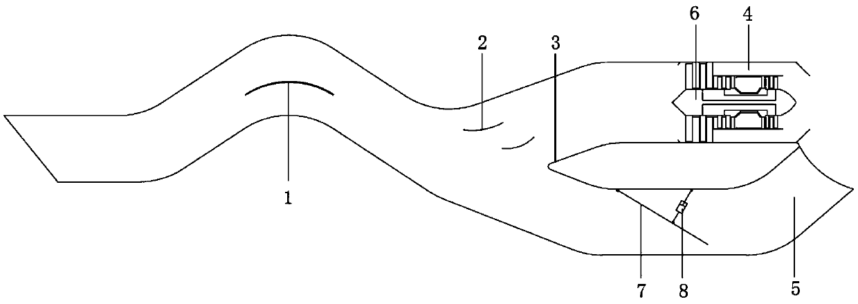
[0016] like figure 1 As shown, a multifunctional aero-engine air intake includes a rectifying wall 1 with the function of measuring momentum energy, a rectifying wall 2 in front of the engine air intake, a fish mouth type diverter ring 3, an engine mounting channel 4 and a foreign object injection channel 5. The rectifying wall 1 with the function of measuring momentum energy passes through the rectifying wall 2 before the engine intake, the fish mouth type diverter ring 3 and the engine installation flow channel 4, and the rectifying wall 1 with the function of measuring momentum energy communicates with the other way The fish mouth type diverter ring 3 is in communication with the foreign matter injection channel 5; the aero-engine 6 is located in the engine installation flow channel 4; a foreign object baffle plate 7 is installed i...


PUM


Abstract

Disclosed are a multifunctional aviation engine air inlet channel and a running method of the multifunctional aviation engine air inlet channel. The multifunctional aviation engine air inlet channel comprises a rectifying wall with a momentum energy measuring function, an engine air inlet front rectifying wall, a fish mouth type shunting ring, an engine installation flow channel and a foreign matter injection flow channel. One path of the rectifying wall with the momentum energy measuring function is connected with the engine installation flow channel through the engine air inlet front rectifying wall and the fish mouth type shunting ring, and the other path of the rectifying wall with the momentum energy measuring function is connected with the foreign matter injection flow channel through the fish mouth type shunting ring. A foreign matter shielding plate is installed in the foreign matter injection flow channel. A hydraulic actuator cylinder is connected between the foreign matter shielding plate and the inner wall of the foreign matter injection flow channel. The foreign matter injection flow channel intersects with the exhaust direction of an aviation engine. The running method comprises the following steps that when foreign matters are sucked by the air inlet channel, radar waves are detected by an aircraft, the aviation engine needs to work in a circulation changing mode, and upward vector pushing force is required by the aviation engine, a control instruction is sent to the hydraulic actuator cylinder by an aircraft central processing unit, so that the hydraulic actuating cylinder works to control the foreign matter shielding plate to be opened.

Description

technical field [0001] The invention belongs to the technical field of aero-engines, and in particular relates to a multi-functional aero-engine air intake and an operating method thereof. Background technique [0002] The air intake of the aero-engine is the flow channel for the aero-engine to inhale air. It is the core component of the aircraft propulsion system and is designed to provide a certain quality of air flow for the aero-engine, which can introduce the free-flowing air in front of the aero-engine into the engine. [0003] Conventional aero-engine inlets are simple straight barrel structures, but they cannot achieve aircraft radar stealth. In order to achieve aircraft radar stealth, the current more advanced aero-engine inlets use S-shaped barrel structures. The radar wave disturbed by the compressor can block a part of the radar reflection wave after passing through the air inlet with special structure, so as to realize radar stealth. [0004] However, no matter...

Claims


Application Information

Patent Timeline
Patent Type & Authority Applications(China)
IPC IPC(8): F02C7/04F02C7/057F02C9/20
CPCF02C7/04F02C7/057F02C9/20
Inventor 石岩周建平王凯张国锋张春艳
Owner SHENYANG LIMING AERO-ENGINE GROUP CORPORATION
Why Eureka
Try Eureka