High-low pressure change-over valve and using method thereof

A high-low pressure conversion and valve core technology, applied in valve details, multi-port valves, valve devices, etc., can solve the problem of fluid transportation that cannot be isolated from the high-pressure end and the low-pressure end, achieve ingenious structural design and reduce energy consumption. and noise effects

Pending Publication Date: 2019-04-16
丁建民
View PDF0 Cites 1 Cited by
  • Summary
  • Abstract
  • Description
  • Claims
  • Application Information

AI Technical Summary

Problems solved by technology

[0003] One of the purposes of the present invention is to provide a high-low pressure switching valve to solve the problem tha

Method used


Image

  • High-low pressure change-over valve and using method thereof
  • High-low pressure change-over valve and using method thereof
  • High-low pressure change-over valve and using method thereof

Examples


Embodiment 1

[0018] Embodiment 1: High and low pressure switching valve.

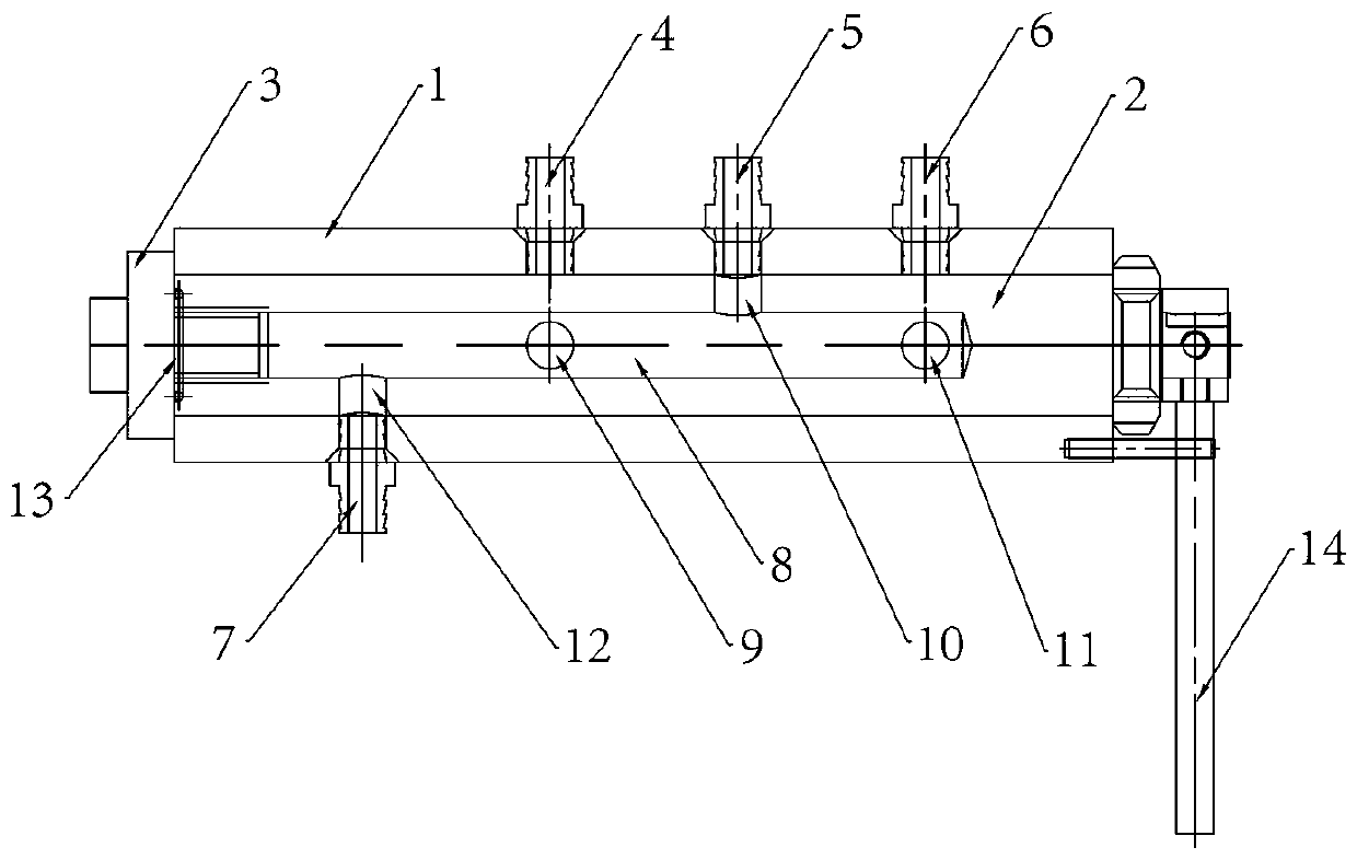
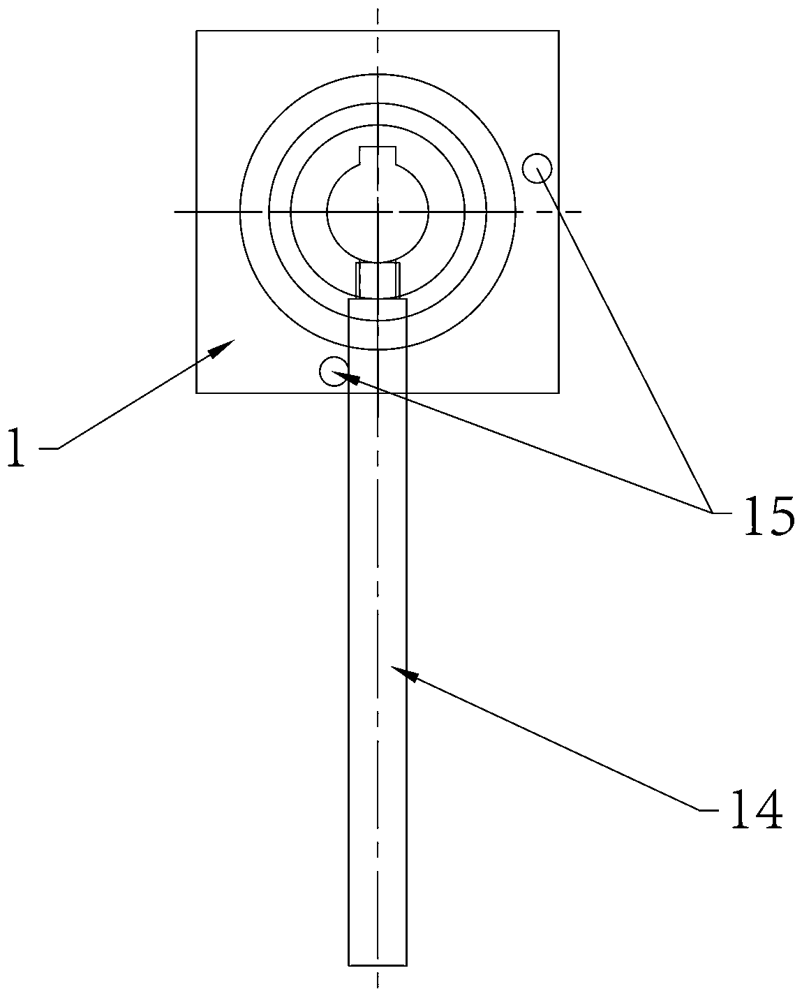
[0019] Such as figure 1 As shown, the present invention mainly includes a housing 1, a valve core 2 disposed in the housing 1, an end plug 3 disposed at one end of the housing 1 to block the valve core, and disposed at the other end of the housing 1 to drive the valve. The core 2 rotates in the casing 1 and other parts such as the lever assembly.

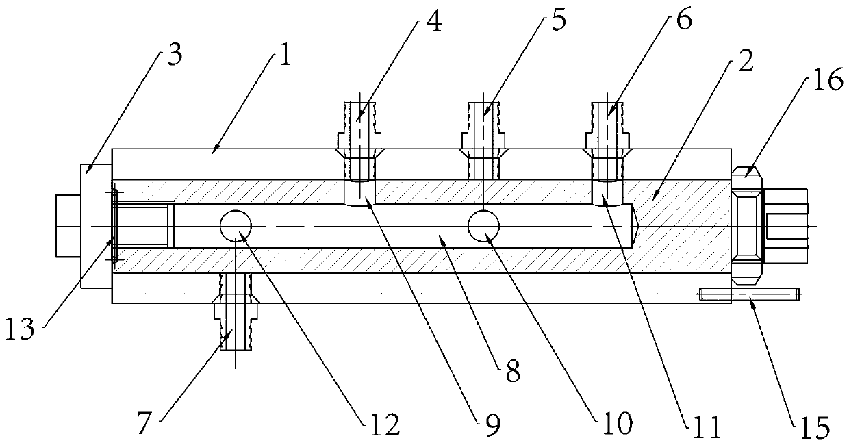
[0020] The housing 1 is in the shape of a square column and has a cylindrical cavity. An end plug 3 is provided at one end of the housing 1, and an air outlet nozzle 4, an air inlet nozzle 5, a liquid inlet nozzle 6 and a liquid outlet nozzle are arranged on the side of the housing 1. Mouth7. The spool 2 is cylindrical and is arranged in the cavity of the casing 1. The spool 2 and the casing 1 are in a rotatable and sealed connection, and the sealing method can be a commonly used mechanical seal. The spool 2 has an axial inner chamber 8, one end of the inner chamber 8 ...

Embodiment 2

[0023] Embodiment 2: The use method of the high and low pressure switching valve.

[0024] The method for using the high and low pressure switching valve of the present invention comprises the following steps:

[0025] 1) Set the high and low pressure switching valve described in Example 1, and connect the liquid inlet nozzle 6 with the fluid outlet of the low pressure end 18 through the first fluid delivery pipe, and the gas outlet nozzle 4 with the gas outlet of the low pressure end 18 through the first connecting pipe Connected, the liquid outlet nozzle 7 is connected to the fluid inlet of the high-pressure end 17 through the second fluid delivery pipe, and the air inlet nozzle 5 is communicated with the gas outlet of the high-pressure end 17 through the second communication pipe, as Figure 4 shown;

[0026] 2) Turn the lever 14 to the low-pressure positioning pin. At this time, the valve core 2 rotates until the air outlet 9 communicates with the air outlet 4, the liquid...


PUM


Abstract

The invention relates to a high-low pressure change-over valve and a using method thereof. The high-low pressure change-over valve comprises a shell body, a valve core, an end plug and a driving leverassembly, wherein the valve core is arranged in the shell body; the end plug is arranged at one end of the shell body and used for plugging the valve core; the driving lever assembly is arranged at the other end of the shell body and used for driving the valve core to rotate in the shell body; an air outlet nozzle, an air inlet nozzle, a liquid inlet nozzle and a liquid outlet nozzle are arrangedon the shell body; the valve core is provided with an inner cavity; an air outlet hole, an air inlet hole, a liquid inlet hole and a liquid outlet hole are formed in the side wall of the inner cavity; when the valve core rotates to a position where the air outlet hole communicates with the air outlet nozzle, the liquid inlet hole and the liquid inlet nozzle communicate with each other; and when the valve core rotates to a position where the air inlet hole communicates with the air inlet nozzle, the liquid outlet hole and the liquid outlet nozzle communicate with each other. The high-low pressure change-over valve provided by the invention is ingenious in structural design; the high-low pressure isolated fluid transportation can be achieved when only one rotating force used for driving thevalve core to rotate is needed; and consequently, the high-low pressure change-over valve, instead of a compressor, can be applied to an air conditioner, and then the energy consumption and the noiseof the air conditioner can be greatly reduced.

Description

technical field [0001] The invention relates to a valve and its use method, in particular to a high-low pressure switching valve and its use method. Background technique [0002] A valve device is a device that uses a movable part to open, close or partially block one or more openings so that fluid can flow through or be regulated. In the process of controlling fluid circulation, the existing valve device can only realize fluid delivery with equal air pressure at both ends. When the air pressure at both ends is different, it cannot realize fluid delivery with isolated high-pressure end and low-pressure end. Contents of the invention [0003] One of the objectives of the present invention is to provide a high-low pressure switching valve to solve the problem that the existing valve structure cannot realize fluid delivery with the high-pressure end and the low-pressure end isolated. [0004] The second object of the present invention is to provide a method for using a high-...

Claims


Application Information

Patent Timeline
IPC IPC(8): F16K11/085F16K27/06F16K31/60
CPCF16K11/085F16K27/065F16K31/605
Inventor 丁建民张玉森石佳龙侯丽辉李耀辉张城玮
Owner 丁建民
Why Eureka
Try Eureka